Thursday, March 15, 2018

How I constructed the sawmill

Preamble

Lineside industries are quite important for my railway as I try to carry out reasonably realistic freight operations when I run full operating sessions (see Managing freight). I decided that, as the Peckforton Estate (through which my hypothetical railway runs) were early adopters of forestry, a sawmill at Peckforton would be a useful way to generate traffic. I recently extended the timber sidings at Peckforton (see How I extended Peckforton Station) which provided a little more space for the sawmill building.  

UPDATE: Interestingly, I have since discovered that a sawmill and timber works was indeed located at Peckforton to serve the output from the Peckforton Estate's forestry. The timber yard has now closed but I aim to investigate its former site and see if any photos exist.

Contents


Introduction

When I decided to finally to fill the space beside the sidings at Peckforton with a structure representing the sawmill, I did a fair bit of research on what sawmills would have looked like in the 1930s. Quite a bit of online information about sawmills originates from Australia or the USA where, of course, the logging industry was a lot better established (eg see Robinson's Sawmill). However, after a fair bit of digging, I did manage to unearth a few bits of information about sawmills in this part of the world - eg http://www.stroudlocalhistorysociety.org.uk/people-places/companies/saw-mill/.  However, there seems to be a dearth of information about period mills - as suggested by this forum post from 2010


The structure

 For the base of the sawmill, I used a piece of 8mm thick plywood, 62cm x 31cm. I marked the centres for eight 5mm diameter holes for the uprights at intervals of 75mm, 15mm from the edge of the base.

 Sixteen 150mm long pieces of 8mm square stripwood were cut ........

...... and one end of each was rounded with a craft knife.

The other end was marked out 4mm x 8mm ........

.... and the ends were cut to form halving joints.

Four of the supports were further trimmed along one other edge to act as corner supports.

Four pieces of 8mm square stripwood were cut to a length of 530mm and marked at 75mm intervals to coincide with the vertical supports.

The supports were similarly marked out with 8mm x 4mm cut-outs 55mm from their bases to form halving joints.

The halving joints were firstly cut with a junior a hacksaw......

.... and then chiseled out with a Stanley knife.

The longitudinal beams were similarly given halving joints and the sides of the structure assembled and glued together with exterior PVA.

The posts were then glued into the holes in the base and 65mm long pieces of 8mm square stripwood glued between each post at the base of each vertical post - as can be seen, I used off-cuts of stripwood to patch-fill some of the gaps (waste-not, want-not).

55mm long pieces of coffee stirrer were then cut ..........

.... and glued along the base of the sides.

Once the cladding on the lower part of the building was completed, the roof was the next part to receive my attention.

The roof

I looked at several online images of sawmills but I was captivated by a 4mm scale model shown in a back issue of Railway Modeller (January 1995, pp 30-32) which showed a structure sporting a curved roof constructed from Belfast trusses. After carrying out some research into Belfast Trusses, which was facinating (eg see https://www.arct.cam.ac.uk/Downloads/chs/final-chs-vol.17/chs-vol.17-pp.75-to-87.pdf), I drafted some rough sketches based on the dimensions of my sawmill and set to work.
 

Belfast trusses

My first job was to produce the curved upper members for the trusses. For these I drew a series of 37mm and 32mm diameter curves on to 4mm thick plywood using a compass fashioned from a strip of card..

Once sixteen curved members had been marked out ........

...... they were cut-out using a coping saw, together with sixteen straight 255mm x 10mm cross beams. One of each pair of curved beams was then marked out in ten equal divisions (numbered 1 to 9, ie ignoring 0 and 10 at each end) and one of each pair of straight beams was marked out in thirteen equal divisions (numbered 1 to 12).
The two beams were placed on a cutting mat with a distance of 1cm between their ends and coffee stirrers were cut to length to firstly, span 1 to 3 and 9 to 10 on the upper and lower beams (the photo shows more clearly what I mean). The stirrers were glued into place with thick superglue as PVA would have taken too long to set.

Next, coffee stirrers were trimmed to fit between 2 and 5, and 8 and 8 on the upper and lower beams.

Then came 3 to 6 and  7 to 7 .......

 ..... followed by 4 to 7 and 6 to 6.

Then came 5 to 5 and 5 to 8. The trusses were beginning to take shape.

Next came 4 to 4 and 6 to 9......

.... followed by 3 to 3 and 7 to 10.

Finally, struts were glued from 2 to 2 and 8 to 11 ......

..... and four diagonally trimmed stirrers at each end othe truss.

Once all the glued joints had set, a curved and a straight cross member was glued on top of the completed truss, using various clamps to hold them in place until the glued had fully set.

Once all eight trusses had been completed .......

...... two pieces of 35mm x 750mm x 4mm thick ply were cut out ......

..... and one side of each truss was glued to it, using the same spacings as used for the supports for the roof.

To help speed-up the glue setting period, an accelerator was used in conjunction with the Superglue. This meant the glue set almost immediately and each truss needed only to be held in place for around a minute before moving on to the next.

Once one side had been secured, the same process was repeated for the other side.

The roof was now ready to be covered.

Before tackling the corrugated iron, I added some purlins to the trusses to provide more support for the roof sheeting. Firstly, a single purlin was fixed across the apex of the roof, ......

..... and then two further sets of purlins midway down each side. 8mm square stripwwod was used for them.

Corrugated iron sheeting

I had originally intended to use aluminium drinks cans for the corrugated sheeting, but these proved difficult to indent without being tempered beforehand and so I resorted to using disposable aluminium foil roasting tins. The foil used for these is quite thick, but not too thick to pass through my paper corrugator.

The roasting tins were opened out and smoothed as much as possible.

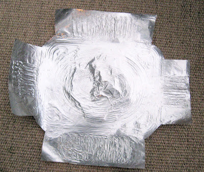
Individual sheets, 45mm x 140mm were then cut out .........

..... and passed through the paper corrugator.

When sufficient sheets had been produced, I started laying them on the roof. I quickly realised that the purlins would be insufficient to support the sheets which were quite flimsy, even after receiving their corrugations. So, a couple of sheets of very thin obeche board were fixed over the roof and the corrugated sheeting panels were glued to this.

Initially, I used gap-filler adhesive, but after a while I realised it was difficult to keep the surface beneath the sheets even and so impact adhesive was used instead.

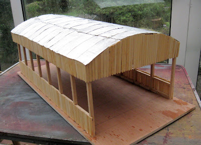
The entire roof was then covered with overlapping sheets and left overnight for the adhesive to harden off.

Cladding

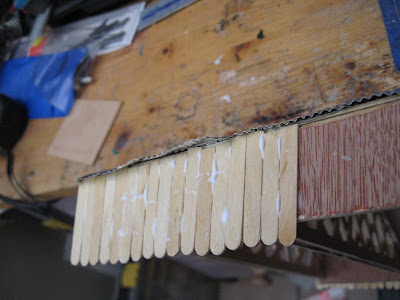
To finish off the roof section, 40mm lengths of coffee stirrer cladding were cut.

 These were glued on with external PVA, ......

......using a tri-square to ensure the cladding remained vertical.

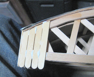
The ends were also covered in coffee stirrer cladding......

...... with each piece being measured in situ .........

...... and then trimmed to size with scissors.

The completed roof section was then test-fitted to the base to ensure all was well.

The guttering

I wanted the roof to be removable so that I could detail and maintain the interior (see How I created the sawmill interior). This meant that I would have to make the guttering bridge the divide between the roof section and the lower structure. I make my guttering from brass and/or copper as I am concerned that plastic would be too vulnerable to accidental damage.

The guttering channels were made from 4mm brass U-shaped sections designed for edging leaded window panes (available from Tempsford Stained Glass) . I find these to be cheaper than normal brass U-channel.

As the sides of the sawmill are longer than the 300mm sections of brass channel, two pieces of channel needed to be joined, using my 70W soldering iron and multicore solder.

The channels were then cut to length, 10mm longer than the sides of the building. The ends of the channel were then snipped 4mm along each of the creases ......

..... and the resulting three tabs folded up .......

....... before being soldered .........

 ....... and tidied up with a file, to form the ends.

20mm long brass nails had their heads snipped off and the top 5-7mm flattened with a file.

The nails were inserted into a hole in the workbench and soldered at regular 90mm intervals to the underside of the channel.

 The solder and ends of the nails were then tidied up with a file.

For the downspouts, two 130mm long pieces of 3mm copper tube were cut, together with two 40mm pieces.

Two 55mm long pieces of 2mm diameter copper wire were cut and inserted into the shorter pieces of tube.

The two short sections were then kinked by about 10mm (the copper wire inside the tube helps to prevent it from creasing at the bends).

A 3mm hole was then drilled in the bottom of the channel at each end .......

 .... and the kinked copper tubes were soldered into the holes.

and the protruding copper wire at the other end soldered into place.

The brackets for the downspouts were made from 60mm lengths of 1mm diameter copper wire.

Each piece was flattened with a hammer ......

..... and then folded around the downspout.

The brackets were then soldered into place and trimmed to leave around 20mm .......

....... and tidied up with a file.

Three brackets were soldered on each lower 130mm section of downspout  at equal distances.

A vee was filed into the longer sections of downspout, 5mm from the end.

The end was then folded by about 45 degrees .....

..... and soldered. The angled end was then tidied up with a file.

The guttering was painted, initially with a coat of with red oxide primer followed by a couple of coats of black acrylic.

2mm holes were then drilled in the fascia of the roof section and the endmost pillars of the main structure to take the brackets. The guttering was test-fitted and then removed to allow the building to be painted.

Painting

The roof and main structure were given a coat of red oxide primer .........

and then given a wash of mucky black acrylics (a mix of black and brown).

When the first coat of acrylics was dry, the woodwork was dry-brushed with a much lighter shade of the base colour to accentuate the woodgrain .......

..... and the corrugated iron sheeting was dry-brushed with a mix of red and brown to highlight peaks in the corrugations.

A nameboard was created in MicroSoft Word using the name John Naylor whom I discovered was a timber merchant in the 1911 census for the area served by the railway. Although John Naylor was given the age of 64 in the census, I have assumed that his 23 year old son (also John Naylor) would have taken over the family business and hence would be in charge in 1932, the period my railway is depicting.

The 40mm x 150mm nameboard was printed on to inkjet glossy vinyl self adhesive sticker paper and then covered with a layer of self adhesive clear film. It was then stuck to a piece of 1.5mm thick plasticard and given a border of 2.5mm wide x 1.5mm thick plasticard before being fixed to the ends of the roof section.

The guttering was then glued into place.

 ..... the upper section of downspout being slotted into the lower section .......

..... to allow the roof to be removable.

Conclusion

Although it looks flimsy, the building is actually quite robust and fits the intended site neatly.


There is still a fair amount of detailing to be done as the open structure gives a clear view of the interior. I am also intending to construct a gantry crane to enable wagons to be unloaded and loaded. It also needs to be properly bedded-in and the area landscaped. I am planning to install an overhead line shaft and pulley system, powered by a mill steam engine, for the various pieces of machinery in the mill (see How I detailed the sawmill).

As indicated above, there seems to be very little information available about sawmills in the UK during the period modelled by my railway and so I have had to use a degree of modellers' licence - drawing on the few images and bits of information I have managed to glean about UK sawmills combined with photos and information about sawmills in the rest of the world.

Saturday, February 10, 2018

How I programmed a Deltang Rx65b for auto station stop with a Tx20

 One of the great built-in features of the Deltang Rx65b receiver/controller is that it includes, as standard, auto-station stop, auto-shuttle and auto-buffer stop. A reed switch, mounted on the loco and connected to one of the pads on the Rx65b will trigger the effect wherever you want it to happen on your railway.

Having previously programmed a Deltang Rx65b receiver for auto-shuttle using a Prog4 Programa module (see How I programmed Deltang Rx65b for auto-shuttle), I decided I wanted to program the receivers in a couple of my locos for auto station stop so the locos would run around the railway slowing down and stopping at each station briefly before accelerating away again.

Although I like to run my railway prototypically with timetabled passenger trains and goods trains managed by a computerised freight management program (see A typical operating session), there are occasions when I just have a train running or two running around while I do some gardening or entertain family and friends with a barbecue.

Rather than using a Programa module, I thought it might be useful for others to see how the programming can be done with a Deltang Tx20 transmitter.

The process

  1. Preparations
  2. Wiring up the receiver and reed switch
  3. Looking up the programming code
  4. Putting the receiver into programming mode
  5. Programming
  6. Testing
  7. Conclusion

1. Preparations

Before doing the modifications to the loco and the receiver, I needed to make a few decisions. 
  • Which locos was I going to use?
  • Which output pad on the receiver was I going to use?
  • Where was the reed switch going to be located on each loco?

Which locos?

 Having fifteen battery powered / radio controlled locos at my disposal (see 2015 Loco Stock Roster), I had to decide which ones would be:
a) the most reliable when left to their own devices
b) had sufficiently large batteries to be able to run for several hours
c) would be the easiest to modify.
 In the end, I selected the two locos which were the among the earliest I added to the railway - Peckett Loco No. 1 (Peckforton)........

and Hunslet Loco No. 3 (Bickerton)

 These were both constructed from GRS (Garden Railway Specialists) kits and both make use of the LGB ToyTrain 0-4-0 motor blocks. They are both powered by three 18650 li-ion batteries and both have Deltang Rx65b receiver/controllers fitted. As they are 0-4-0s, they don't have any pony trucks or bogies to become derailed and their mechanisms are very reliable. They are also both easy to dismantle to gain access to the receivers.

Which output pad would I use?

 I opted for Pad 8 on the Rx65b (shown in red).

This is because its default setting is for Channel 1 servo output, which I seldom use, and also because it is close to the three negative pads one of which I would be using for a capacitor (see below).

Where was the reed switch going to be mounted?

Another reason for choosing two locos which use the ToyTrain loco blocks was that their undersides have a recess which is ideal for mounting the reed switch.

Furthermore, I realised I could make use of the wiring system which was built into the motor blocks for the wheel pickups (see below)

2. Wiring up the receiver and the reed switch

This is probably the trickiest bit of the whole process. It needs a soldering iron with a small bit and a steady hand.

Connecting a 0.1uF ceramic capacitor

To minimise the possibility of electromagnetic interference (EMI) disrupting the connection from the reed switch to the receiver a 0.1uF capacitor needs to be soldered from the output pad to the negative supply.
These can be bought cheaply on eBay (I think I bought 20 for £2.50 including postage). I soldered mine between Pad 8 and the nearest negative pad.

I then soldered a wire to Pad 8 and another wire to another negative pad (the grey wire on Pad 9 is being used as a trigger for a sound effect on the Dallee Sound Card).

The receiver was then shrouded in a shrink wrap sleeve.

 I then removed the bottom plate of the motor block by unscrewing the screws holding it in place and re-installed the L-shaped metal connectors originally used for the track pick-ups. I bent up the last 10mm of these through 90º.

I then drilled a couple of 2mm diameter holes in the base plate after carefully measuring the location of the two metal 'spikes'. The base plate was then threaded over the spikes.

The spikes were then folded over and a reed switch soldered on to them.

An LGB push connector was soldered to the end of the (orange) wire leading to Pad 8 and the end of the negative wire was soldered to the central pin of a sub-miniature SPDT toggle switch. Another black lead was soldered to another of the pins and an LGB push connector soldered to the other end.

The switch was mounted discretely beneath the saddle tank

This switch will be used to disable the auto station stop feature by isolating the reed switch. This will enable be to use the loco for normal duties.

The LGB connectors were then pushed on to the ends of the old track pickup contacts protruding from the top of the motor block (the central orange and black wires). The other two wires connect the motor to the Rx65b.


3. Looking up the programming code

The codes needed for reprogramming Deltang receivers are located on the Deltang website. The programming chart for the Rx65b receiver controller is startlingly long - a reflection of the potential and complexity of this little technological marvel. It can seem a bit daunting at first sight, but it does actually make a lot of sense if you persevere with it.

The section I needed for the auto station stop is in Menu 3 under the heading Automation.
Automation
3 1-8 = P1-P8

8 = Buffer Stop
[BUFFER1]

Time to stop:
1-6 = 1-6 seconds
Reactivate trigger:
1-6 = 10-60s
(time to 'back out')

ONE pad can detect external trigger to control H1
Action: Slow to a stop
Close throttle to rearm (manual).

3 1-8 = P1-P8

9 = Stop & Reverse
[BUFFER2]

Time to stop:
1-6 = 1-6 seconds

Fixed pause time:
1-6 =
4,8,15,30,45,60s
Random pause time:
7 = 4-8s
8 = 8-15s
9 = 15-30s
10 = 30-45s
11 = 45-60s

ONE pad can detect external trigger to control H1
Action: Stop-Pause-Reverse (auto).

3 1-8 = P1-P8

10 = Station stop and continue
[BUFFER3]

Time to stop:
1-6 = 1-6 seconds

Pause time:
As above
ONE pad can detect external trigger to control H1
Action: Stop-Pause-Continue (auto).

Looking at the third option in this section I noted down the series of codes I needed for the auto station stop:

3, 8, 10, 6, 11

Cross referencing this with the bottom row of the chart, you will see that each number instructs the receiver to do something:
  • 3 = Menu 3
  • 8 = Pad 8
  • 10 = Auto station stop
  • 6 = 6 seconds to slow down to a stop
  • 11 = 45-60 seconds stopping before restarting

4. Putting the receiver into programming mode

I could have used a Prog4 (eg see Programming with a Prog4), a Prog3 eg see Programming with a Prog3) or a Tx20 (see Programming with a Tx20). I opted for using a Tx20 as this is my preferred programming technique. I find it to be the quickest and easiest method, particularly for a relatively simple programming task such as this.

Firstly the receiver in the loco was bound to the Tx20 by:
  1. switching on the receiver
  2. waiting for around 15 seconds until it went into bind mode (its LED flashed rapidly).
  3. holding down the bind button on the transmitter
  4. switching on the transmitter (with the bind button held down)
  5. releasing the bind button
  6. waiting until the LEDs on the receiver and the transmitter stopped flashing to show they were now bound
 I then put the Rx65b into programming mode by:
  1. switching off the receiver
  2. holding down the F1 (Channel 2) and F2 (Channel 4) button on the Tx20
  3. switching on the Tx20 (with the buttons still held down)
  4. switching on the receiver
  5. checking that the receiver was in programming mode (signified by very rapid flashing of its LED)
  6. releasing the buttons on the Tx20
 

 5. Programming

The LED on the Rx65b was flashing once per second. This showed it was ready to receive instructions for Menu 1. As I wanted to change items under Menu 3:
  1. I clicked the Direction Switch on the Tx20 in the REVERSE direction. 
  2. The LED on the Rx65b flashed rapidly
  3. When I returned the Direction Switch to the central NEUTRAL position the LED started flashing twice per second. 
  4. I then flicked the Direction Switch in REVERSE once more and returned it to NEUTRAL 
  5. The LED on the Rx started flashing three times. This meant it was ready to receive instructions for Menu 3
  6. I flicked the Direction Switch to the FORWARDS position and back to NEUTRAL to confirm that was what I wanted.
The Rx65b was now waiting for the next code number (ie which pad I wanted to change). I wanted to use Pad 8 and so:
  1. I flicked the Direction Switch in the REVERSE direction 7 times to increment the flashes (pausing between each flick of the switch and sometimes counting the number of flashes to see how far I had reached)
  2. I checked that the LED on the Rx65b was flashing 8 times
  3. Then I clicked the Direction Switch in the FORWARDS direction to confirm this setting
The Rx65b was now waiting to be told what instruction was being attached to Pad 8. I was wanting to use it as the input from the reed switch for auto station stop (ie the value of 10) and so:
  1. I flicked the Direction Switch in the REVERSE direction 9 times to increment the flashes (pausing between each flick of the switch)
  2. I checked that the LED on the Rx65b was flashing 10 times
  3. Then I clicked the Direction Switch in the FORWARDS direction to confirm this setting
The next setting was for the number of seconds I wanted for the loco to slow down (ie 6 seconds) and so:
  1. I flicked the Direction Switch in the REVERSE direction 5 times to increment the flashes (pausing between each flick of the switch)
  2. I checked that the LED on the Rx65b was flashing 6 times
  3. Then I clicked the Direction Switch in the FORWARDS direction to confirm this setting
Finally, the Rx65b was waiting to be told how long the loco would wait in the station before resuming (ie 45-60 seconds, represented by 11 flashes) and so:
  1. I flicked the Direction Switch in the REVERSE direction 10 times to increment the flashes (pausing between each flick of the switch)
  2. I checked that the LED on the Rx65b was flashing 8 times
  3. Then I clicked the Direction Switch in the FORWARDS direction to confirm this setting
At this point the LED on the Rx65b remained on steadily, showing that it had processed all the information I had just given it. The loco was now ready for testing.

6. Testing

Bench testing came first. Once I had checked all the wiring was correct, I powered up the loco and inverted it. I used the transmitter to get the wheels to start rotating as if the loco was moving forwards. I then waved a magnet over the reed switch and to my delight (and relief) the wheels slowed and stopped. After around 50 seconds, the wheels started rotating once more. All seemed to be fine. I tested it another couple of times, at different speeds and with the wheels rotating in reverse.

I was then ready for testing outside on the track. I fixed a magnet to one of the sleepers in the station area, fixing it down with a couple of twists of wire. When I ran the loco over it, nothing happened. I then attached another magnet to the first, thus doubling its height (and increasing its strength) and this time the loco coasted gently to a halt as it passed over the magnet.

I then made a video of the next test run (my camera running out of battery at the last moment!

Conclusion

The most difficult part of this modification is, as has been stated, soldering the leads on to the receiver. I would suggest, if you are not confident with handling a soldering iron, that you ask someone who is to do it for you as a favour. When I was running RC Trains, I had a couple of receivers returned to me which had suffered damage because people had overheated them with soldering irons. The PCB tracks on the Rx65b are quite delicate and can easily be broken if too much heat is applied.

Other than that, deciding where and how to fix the reed switch is the next most difficult task. With a Tx20 (or even a Prog3), the actual programming is a breeze and probably the most satisfying part of the process.

The built-in auto capabilities of the Rx65b are a nice added bonus and it does seem a shame not to make use of them in some way. I hope this blog post encourages you to have a go.

Thursday, February 08, 2018

How I created a latching on/off output from a Deltang Rx102 receiver

The outputs from the Deltang Rx102 receiver can be reprogrammed so the default servo outputs become on/off outputs (see How I reprogrammed a Deltang Rx102 receiver). This means the outputs can be used to directly trigger sound effects on a sound card (such as the whistle) or can be used to turn on and off LEDs and other accessories. However, the outputs are momentary - ie they stay energised only while the button is pressed on the transmitter or the switch is clicked. The outputs revert to their original states when the button is released or the switch is turned off.

To change this situation, I decided to experiment with a couple of latching bistable (flip flop) modules which can be purchased through eBay for a modest price (just search for latching bistable module). Once energised, these modules keep the supply connected until they are energised again - ie they are latching as opposed to momentary. They range in price from around £1.50 to £5-£6. I bought a couple of different types of reasonably priced modules and went for solid-state versions rather than relay operated ones, as they operate from 3v and are smaller in size.

They both seemed to have a similar spec. - (3-24v, up to 5A load) - though one had six legs and the other had five.

I had previously used a couple of these modules to operate the interior lighting in some of my coaches (see How I added interior lights to my coaches). I didn't want to mount switches on or underneath my coaches and so decided I wanted the lighting to come on when a magnet was waved over their roofs. A reed switch triggers the module and the lights stay on until the magnet activates the reed switch again.

As with sound cards, the modules are activated by connecting the trigger input to the 0v (ie negative) supply from the battery. As I had already reprogrammed the Rx102 to provide 0v outputs on three of the pins, the Rx102 was already set-up for the module (see How I reprogrammed the outputs of a Deltang Rx102).

The wiring for the module is very straightforward.
The negative supply is shared by the receiver, the module and the LEDs. The positive supply is shared by the receiver and the module. The switched output from the module is connected to the positive legs of the LEDs and the trigger input on the module is connected to the Pin on the receiver which has been reprogrammed to provide a 0v output in response to a signal from the transmitter.

Note: The value of the load resistor protecting the LEDs will vary depending on the voltage of the batteries (the Rx102 has a maximum voltage of 10v!)

The connections on the module were made using a couple of JR servo plugs.

Once everything had been wired-up, the circuitry was tested. Pressing the bind button on the transmitter (Channel 5), makes the output from Pin 5 go low (ie down to 0v) which activates the latching module and turns on the LEDs. They remain on until the bind button is pressed again.

[Awaiting video]

However, when I tried exactly the same circuitry with one of the five-pin modules, it did not work in response to receiving 0v from the receiver. By-passing the output from the receiver and connecting the trigger input on the module directly to the negative lead from the batteries was successful. The output from the pin on the receiver must somehow confuse the second module - it might be because the internal voltage of the receiver is 3.2v while the supply is 6v and so the differential between high and low is insufficient to trigger the module. Fortunately, this does not seem to confuse the first module or the soundcards with which I have used the 0v outputs from the receiver (ie the MyLocoSound and the MTroniks Digisounds cards).

If you use two battery packs (eg a 6v pack for the receiver and a 12v pack for the accessory you want to switch on and off), then negative leads from both battery packs must be connected to the latching module. Do not connect both positive leads together!

Wednesday, February 07, 2018

How I reprogrammed a Deltang Rx102 with a Prog3

Introduction

The Deltang Rx102 receiver can be reprogrammed to change the default servo outputs from the pins to on/off outputs. This means that......
  • LEDs connected to the receiver can be turned on and off remotely by a transmitter, 
  • other devices can be operated through a relay 
  • or sound effects on sound cards can be triggered 
 ....... by pressing buttons, flicking switches or wiggling joysticks on your transmitter.

In my case, I wanted to reprogram my Rx102 so that it could be used to trigger the additional sound effects on a MyLocoSound steam soundcard, including as the whistle and safety valve.

Most sound cards which have additional sound effects (eg the MTroniks DigiSound, the Dallee and the Phoenix sound cards) require their inputs to be connected to 0v to trigger these additional sounds (see How to interface sound cards with Deltang receivers). Some receivers, such as the Deltang Rx65b are already programmed to provide 0v outputs for sound triggers, but the Rx102 does not. However, with a Deltang Prog3, reprogramming the outputs of the Rx102 is relatively easy.

Before ploughing through the instructions set out below, I would suggest you watch the video which I have made, demonstrating the process. It should, hopefully, make what follows a lot more understandable.

Contents

  1. Preparations
  2. Binding the receiver to the Prog3
  3. Programming the Prog3
  4. Transmitting the instructions from the Prog3 to the receiver
  5. Checking
  6. Conclusion

1. Preparations

 i. Deciding what you want to do

The first job is to decide what you want the outputs from the receiver to do. You can change any of the outputs to give:
  • Servo outputs
  • On/Off outputs
  • Auto directional lighting outputs
The default outputs from the signal pins on the receiver are:
Pin 1 - Servo output in response to Channel 1 on the transmitter
Pin 2 - Servo output in response to Channel 4 on the transmitter
Pin 3 - Servo output in response to Channel 3 on the transmitter
Pin 4 - Servo output in response to Channel 2 on the transmitter
Pin 5 - Servo output in response to Channel 5 on the transmitter
Pin 6 - Auto directional lighting (forward)
Pin 7 - Auto directional lighting (reverse)
Pin 8 - Servo output in response to Channel 4 on the transmitter (Pin 8 is located on the side of the receiver)
So, any pin on the receiver can be reprogrammed to respond to any Channel in any way you choose.

I decided that I wanted my receiver to be reprogrammed to give:
  • 0v on Pin 5 when Channel 5 went low (ie when the Bind Button on my Deltang transmitter was pressed)
  • 0v on Pin 4 when Channel 3 went high (ie when the Direction Switch on my Deltang transmitter was clicked in reverse)
  • 0v on Pin 3 when Channel 3 went low (ie when the Direction Switch on my Deltang transmitter was clicked forward)
 My next task was to consult the programming chart for the Rx102 on the Deltang website to discover what codes needed to be sent to the Rx102 to effect the changes I wanted.

ii. Consulting the programming chart

At first sight, the chart on the website can look a bit daunting. However, it actually makes a lot of sense when you work out how the various columns map on to the things you want to change on the receiver.

The part of the chart which was of interest to me was the second row (shown in bold):

2. PROGRAMMING OPTIONS:

Level 1 Level 2
Output number
Level 3
Output type
Level 4
Channel number
Level 5
Other choices
Information
1 flash 1-8 flash = P1-8 1 flash = Servo 1-7 flash = Channel 1-7
(eg: 1,2,1,4 = P2, Servo, Ch4)


1 flash 1-8 flash = P1-8 2 flash = On/Off led 1-7 flash = Channel 1-7 1 flash = ON when Ch is low
2 flash = ON when Ch is mid
3 flash = ON when Ch is high

4 flash = OFF when Ch is low
5 flash = OFF when Ch is mid
6 flash = OFF when Ch is high
Off in other positions (eg: 1,3,2,5,1 = P3, On/Off, Ch5 Low ON)


On in other positions
(6 options from v110-3)


The first column just tells the receiver the menu from which we are selecting our instructions. For the Rx102 there is just this one menu (for the Rx65b there are 13 different menus). The first code number is therefore 1.

The second column determines which output pin we want to change. I decided to start off by changing Pin 5 as I wanted to use this to trigger the whistle sound effect when the bind button on the transmitter is pressed. So, the next number I needed in my list of instructions for the receiver was 5 (ie pin 5)

The next column tells the receiver what action you want it to perform on the chosen pin. I wanted the on/off option (rather than controlling a servo or have directional lighting) and so my next instruction code for the receiver was 2.

The fourth column determines which Channel the pin on the receiver will respond to. In my case, I was wanting Pin 5 to respond to Channel 5 (ie the Bind Button) and so my fourth instruction was 5.

The fifth column tells the receiver how it must respond when receiving a signal on the chosen channel. In my case, I wanted the pin to give 0v when the Bind Button was pressed. Pressing the Bind Button on the transmitter makes Channel 5 go low - so I needed to use instruction 4 (ie turn OFF the output from Pin 5 when the signal from the transmitter on Channel 5 goes low).

iii Working out the codes I needed to send to the receiver

This gave me the following series of codes for the receiver:

1, 5, 2, 5, 4
ie:
  • 1= Menu 1
  • 5 = Pin 5
  • 2 = On/Off
  • 5 = Channel 5
  • 4 = 0v when the channel goes low
For my the other changes I wanted to make to the receiver, the codes are:

 1, 4, 2, 3, 6
ie
  • 1 = Menu 1
  • 4 = Pin 4
  • 2 = On/Off
  • 3 = Channel 3 (Direction switch)
  • 6 = 0v when the channel goes high (ie when the direction switch is in reverse)
..... and

 1, 3, 2, 3, 4
ie
  • 1 = Menu 1
  • 3 = Pin 3
  • 2 = On/Off
  • 3 = Channel 3 (Direction switch)
  • 4 = 0v when the channel goes low (ie when the direction switch is forward)
You might need to take a little while to grasp the logic of this - particularly how the values in the fifth column relate to the response you want to get when a button, switch or joystick is operated on the transmitter. Just remember, that moving a joystick, flicking a switch or pressing a button will make a particular channel go high or low (or higher or lower if it is a proportional control).

2. Binding the receiver to the Prog 3

The Prog3 is very much a stripped down transmitter and so the bind process is similar to any transmitter.

The first job is to put the receiver into bind mode. I had an earlier version of the Rx102 which requires a manual approach to putting the receiver into Bind Mode.
1. The receiver was turned off.
2. The large (black) bind plug was connected to signal pins 5 and 7
3. The receiver was turned on
4. The LED on the receiver flashed rapidly showing it was in Bind Mode
5. The Bind Plug was removed
NOTE: If you have one of the later Rx102s (marked Rx102(AB)) then it will go into Bind Mode automatically. Make sure the transmitter and Prog3 are turned off. Turn on the receiver and wait ten seconds. The receiver should go into Bind Mode (ie the LED on the receiver should flash rapidly).

To put the Prog3 into Bind Mode, I:
  1. Held the Bind Button on the Prog3 down
  2. Turned on the Prog3 (with the button still held down)
  3. Released the Bind Button
  4. The LED on the Prog3 and the LED on the Rx102 flashed once a second
  5. When the LEDs stopped flashing the bind process was completed.
  6. The LED on the Rx102 started flashing three times, then pause, three times, etc to show it was communicating with the Prog3
NOTE: Sometimes the bind process doesn't work first time. If so, turn off the receiver and the Prog3 and try the process again, moving the receiver and Prog3 to a different orientation. Also make sure there are no other transmitters on close by.

I then turned off the Rx102 to make sure I didn't accidentally reprogram it before I was ready.

3. Programming the Prog3

The Prog3 needed to be programmed with the first of the codes shown above (ie 1, 5, 2, 5, 4)

The first five pins on the Prog3 represent the five columns (or Levels) on the programming chart. So, I needed to change the values on each of the pins to those needed to reprogram the Rx102.

The 'values' on each pin are shown as a series of flashes of the LED on the Prog3.
  • 1-flash means the value on that pin is 1, 
  • 2-flash means it's 2, 
  • 3-flash means it's 3,
  • and so on........
 To change the values on each pin, we use the Bind Plugs which come with the Prog3. The Large Black Bind Plug increases the number of flashes on the pin it's connected to. The Small Red Bind Plug decreases the number of flashes on the pin.

When a Prog3 is delivered new, the values on each pin are 1, and so the Large Black Bind Plug is needed to increase them.

To check the value on Pin 1, I connected the Large Black Bind Plug to Signal Pin 1 and Negative Pin 1.

The LED started by flashing once, then pausing, showing the pin had the expected value of 1. I quickly removed the Bind Plug so it wouldn't increase to 2. (If it had, I would have used the Red Bind Plug to reduce it - the Red Bind Plug is connected to Signal Pin 1 and Positive Pin 1 (ie the middle pin)).

To change the value on Pin 2, I connected the Large Black Bind Plug to Signal Pin 2 and Negative Pin 2.

The LED gave 1-flash when it was connected, it then repeated 1-flash and went on to 2-flash, repeated, then 3-flash, repeat, 4-flash, repeat, then 5-flash. At this point I removed the Bind Plug and the LED repeated its 5-flash before going out. This showed the value on Pin 2 was now 5, as required.

I repeated the process of putting the Large Black Bind on Pin 3 until it showed 2-flash. Then Pin 4 until it showed 5-flash and finally Pin 5 until it showed 4-flash.

To 'fix' these values, the Bind Button was pressed on the Prog3.

The Prog3 was now ready to transmit the information to the Rx102.

4. Transmitting the information from the Prog3 to the Rx102

I first checked that the transmitter to which the Rx102 had been bound was off. It's not essential, but it is advisable so that nothing untoward happens.

The Rx102 was switched on and I waited until it started flashing three times, pause, three times etc, to show it was in communication with the Prog3.

I then pressed the Bind Button on the Prog3 and the LED on the Rx102 flashed rapidly to show it was receiving the information.

I released the Bind Button and the LED on the Rx102 returned to 3-flash.

The programming was now completed.

I turned off the Rx102 to make sure the new instructions were processed and also turned off the Prog3

5. Checking

To make sure all was well, I wanted to check that the instructions had been correctly transmitted and also that they were giving the output I was expecting.

I turned on the transmitter to which the Rx102 had previously been bound (in my case a Tx20) and then turned on the Rx102.

Once the LED on the Rx102 was glowing steadily, showing it had 'found' the Tx20, I connected an LED to Pin 5 of the Rx102. I had wired up an LED to a servo plug, the white lead (yellow on other servo leads) to the +ve leg of the LED and the black lead (brown on other servo leads) to the -ve leg of the LED. There is no need to connect a resistor in series with the LED as the Rx102 outputs are buffered with suitable resistors. The middle red lead was left unconnected.

When initially connected, the LED glowed, showing it was receiving 3.2v from the receiver (ie the output from Pin 5 was on).

I then pressed the Bind Button on the Tx20 and the LED went out - showing the output from Pin 5 was dropping to 0v. As expected.

I then reprogrammed the other two pins in the same way

Conclusion

The ability to reprogram the outputs of the Rx102 makes them even more versatile. There is no need for additional circuitry connected to the output pins for switching on lighting or accessories or triggering sound effects.

NOTE: The switched outputs are non-latching and so some sort of circuitry will be needed if the switch on the transmitter is also momentary. A latching flip-flop module such as this (£3 each on eBay) can be connected to the pin to provide a latching output.

See - How I created latching on/off outputs from a Deltang Rx102 receiver or see How I used a latching flip flop switch with reed switches for lighting circuits in my coaches)


Saturday, February 03, 2018

How I reprogrammed a Deltang Rx102 with a Prog4 module to operate a MyLocoSound sound card

Preamble

Although I have previously written a post about reprogramming the Rx102 receiver (see How I reprogrammed a Deltang Rx102), things have changed a little since then and so I felt it was time I replaced that post with a more fully detailed, up to date version.

I wanted to reprogram an Rx102 receiver so that I could use spare pins to trigger the effects on a MyLocoSound sound card. The MyLocoSound card (like most sound cards) need a 0v signal to trigger additional effects. The default outputs from the Rx102 are either for servos (on Pins 1 to 5) or for directional lighting (on Pins 6 and 7). As I wanted to use my Deltang Tx22 transmitter to trigger the effects, I wanted to use the Bind Button (Channel 5) and the Direction switch (Channel 3) as sound effect triggers. For more information on interfacing the MyLocoSound card with Deltang receivers see How to interface Deltang receivers with sound cards - MyLocoSound

The outputs could just as easily be reprogrammed to provide 3.2v positive outputs to power LEDs eg for interior lighting (see below). There is no need to include a load resistor when wiring up LEDs to the signal pins of the Rx102 as the receiver outputs include appropriate resistors.

Contents


The Prog4 Programma module

 The Prog4 (like the Prog1, Prog2 and Prog3) is a modified Rx102 receiver. The most significant difference is that the Prog4 has a rather prominent push button mounted on one side. This is the bind button (on the other Prog modules, it is also used for transmitting the programming instructions).

The Prog4 needs to be connected a computer with an RS232/USB (CH340) cable.

I got mine via eBay by searching for PL2303TA TTL to RS232 Converter Serial Cable
. The first one I purchased failed to work (not sure why) but the second one (and a third) worked well so it might be worth persevering if things do not work out OK the first time you try.

When it arrived, I connected the lead to the Prog4:
  • Black lead to the Bottom Pin 7
  • Red lead to Middle Pin 7
  • Green lead to Upper Pin 7
  • White lead to Upper Pin 6

Installing the software (on a Windows 10 PC)

Before installing the software, I needed to download and install a driver for the interface cable. This was downloaded from https://serialio.com/drivers-and-set-up-usb-rs-232-adapter-in-windows. As indicated on the web page, once the .EXE file was downloaded and saved, I had to install it 'as an administrator'. I right-clicked on the saved file and selected 'Run as administrator'.

Once that was installed I downloaded CoolTerm from http://freeware.the-meiers.org/ . The zipped file needed to be extracted which I did by right-clicking and selecting Extract all.

 I dragged the resultant folder on to my desktop so that I would know where to find it in future (the program does not install to the programs list in the Windows menu).

Setting up CoolTerm

Before starting up the program, I inserted the USB lead into a USB socket. The driver had installed successfully (I had rebooted the computer to make sure) and so there were no error messages. The LED on the Prog4 came on to show it was connected.

In the CoolTerm folder on the desktop were a couple more folders and the CoolTerm.exe file. I doubled clicked this to start up the program.


The program loaded OK and the LED on the Prog4 started flashing 3 times, then pause, three times, etc. (ie 3-flash) to show the software was communicating with it.

Before using the software, I needed to set it up for the Prog4. Clicking on the Options Button ......


.......... took me to the Options screen.

On my computer and with my USB socket, the Prog4 was showing up as COM3. You might need to click on the 'Re-Scan Serial Ports' button to get your Prog4 to show up. If it doesn't you might need to try another USB socket (or buy another lead - see above). Your USB lead/Prog4 might show up on a different port (it was COM7 on my old laptop).

The settings needed to be changed to those above, ie:
  • Baud rate = 115200
  • Data bits = 8
  • Parity = Even
  • Stop Bits = 1
  • XON check box ticked
I also clicked on the 'Receive' settings and ticked the Ignore receive signal errors check box.

The program was now ready to send information to the Rx102

Binding the receiver to the Prog4

Before the programming info could be sent to the Rx102, the receiver needed to be bound to the Prog4. The receiver was put into Bind Mode by connecting the black bind plug (supplied with the receiver) across signal Pins 5 and 7 (ie the uppermost row) and turning on the receiver.

The LED on the receiver started flashing rapidly showing it was in Bind Mode and so I removed the bind plug.

I removed the Prog4's USB plug from the computer and then, holding down the bind button on the Prog4, I re-inserted the USB plug - this puts the Prog4 into Bind Mode.

I removed my thumb from the bind button and the LEDs on the Prog4 and the Rx102 flashed once a second in unison and then after a few seconds they both started flashing three times and pausing, three flashes, pause, etc. The Prog4 and the Rx102 were now bound together (Note: if the Rx102 had previously been bound to a transmitter such as the Tx22, it will not forget that bind).

The Prog4 was now ready to reprogram the receiver.

Creating the text files

The easiest way to reprogram a receiver with the Prog4 is to create a series of text files with the instructions for the receiver. I wanted to set up my Rx102 so that I could use the bind button and direction switch on my Tx22 transmitter to trigger sound effects on a MyLocoSound sound card. The Bind Button sends Channel 5 low when it is pressed and the Direction Switch sends Channel 3 high or low depending on which way it is switched.

To discover what instructions need to be sent to the receiver, I consulted the table for the Rx102 on the Deltang website. (click on the image to enlarge it).

This table showed that the codes needed to reprogram pin 5 on the receiver were:

1,5,2,5,4
  • 1 = menu one
  • 5 = Pin 5
  • 2 = on/off
  • 5 = Channel 5
  • 4 = Off when the channel is Low
In other words, when the Bind Button is pressed on the transmitter (sending Channel 5 low), the receiver will turn off the output from Pin5 (ie the output from Pin5 will become 0v)

The codes for the Direction Switch were:

1,3,2,3,6

ie. The output from Pin3 will become 0v when the Direction Switch is flicked in reverse (ie sends Channel 3 high).

And.......

1,4,2,3,4

The output from Pin4 will become 0v when the Direction Switch is flicked forward (ie sends Channel 3 low).

I used Notepad on my computer to create the text files (if you can't find it, type Notepad into the search box on the bottom left of the screen and press return). NOTE: Although you can save text files from MS Word, the files include all sorts of additional gobbledegook which could confuse the Prog4.

The text file for the Bind Button instructions........

The text file for the Reverse Direction Switch ......

and the text file for the Forward Direction Switch......

 Each text file was saved (in a folder inside the CoolTerm folder) so they could be used later.

Sending the text files to the receiver

 With the receiver bound to the Prog4 and the Prog4 communicating with the computer through CoolTerm, I was now ready to send the instructions to the Rx102.

I needed to unplug the USB lead and re-insert it because the Prog4 had gone to sleep. It switches off after 5 minutes if nothing is happening.

The first job was to open the connection between CoolTerm and the Prog4. I clicked on the Connect button.

Once connected, I then clicked on the Connection menu and selected Send Textfile...


I navigated to the folder where I had stored the text files and then clicked on the first of them and clicked the Open button.

The information in the text file was sent from the computer to the Prog4 and then on to the Rx102.

The other two text files were also sent in the same way. I got a series of messages in the CoolTerm window to show the files had been transmitted OK
Note: these messages do not always appear straight away, even though the files have been transmitted successfully. The best way to find out if they have worked is to check the receiver (as below).

The receiver was turned off (to save the changes).

Checking

 To check that the receiver had been programmed correctly, I wired-up an LED to a servo plug. There is no need to include a resistor with the LED as the Rx102 includes load resistors in the circuitry for the output pins. The black lead from the servo plug was connected to the negative leg of the LED and the white (or yellow) lead was connected to the positive leg of the LED. The middle (red) lead from the plug was left unconnected.

The receiver was bound to the Tx22. The LED was connected in turn to Pins 3, 4 and 5 and the relevant button or switch operated on the transmitter. When first connected, the LED glowed steadily but when the switch or button was operated on the Tx the LED was extinguished showing the output was going from 3.2v to 0v.

I will attempt to make a video showing this process but it will have to be a combination of screen captures and live action and so it might take a while to figure out the best way to achieve this. In the meantime, I hope the information above is useful.