Around a week of almost unbroken sunshine has provided a real opportunity and incentive to get busy in the garden. Focused input on the railway has resulted in the completion of a few maintenance jobs, a couple of construction projects and more than a few running sessions.
Maintenance
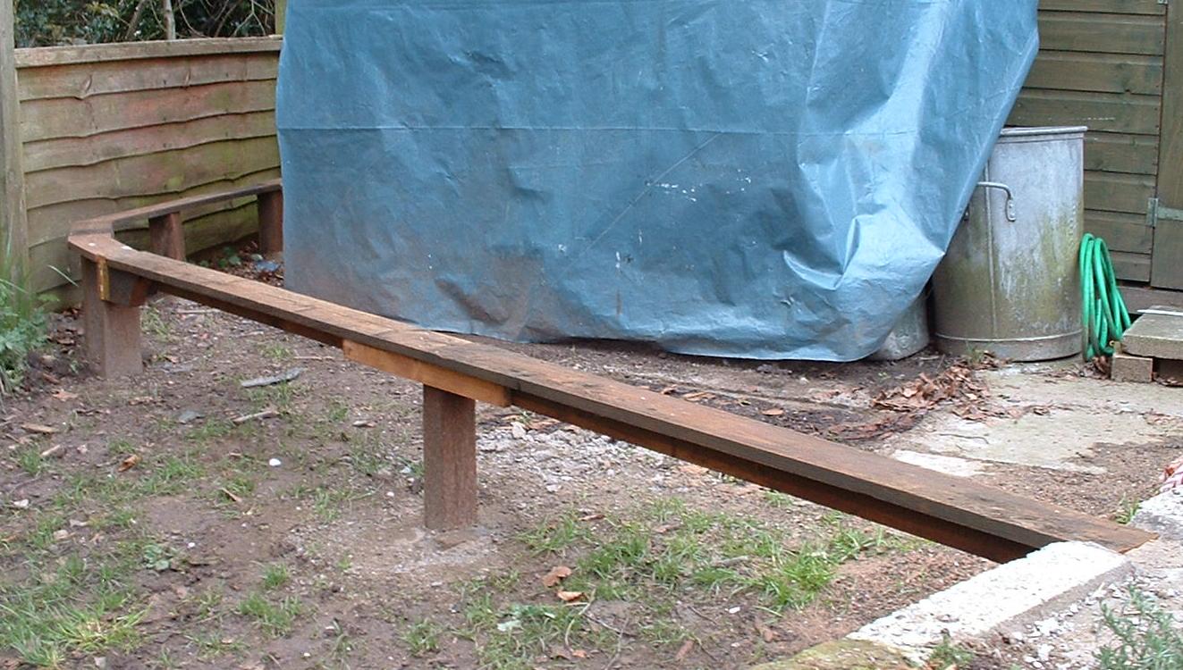
Replacing a rotten timber support post
After boasting in one of my postings that I have never had a problem with my approach to embedding timber support posts in concrete, one of my posts rotted through completely over the winter. This particular post was one which I had recycled from a former fence and so was not in the prime of life when I deployed it, but I would have expected it to last more than seven years.
Rather than trying some sort of temporary remedial action, I decided to remove the concrete foundation in its entirety and replace the post with something more substantial. The concrete base came out of the ground a lot more easily than I expected with some gentle leverage from a garden fork.
A section of well treated 4" square fence post was cut to length and a stiff 3:1 mix of sand and cement was mixed (with some hard-core from the old concrete base) and the post was fixed into place.
A new piece of fence rail was cut to length, covered in roofing felt and the original piece of rail re-instated. The whole process took no more than a couple of hours.
Improving the rail-joints on the moveable bridges
Ever since the tracks were fist laid, I have relied on the positioning of the bridges alone to align the tracks between the moveable bridges and the rest of the system. Over the years, I've had to wedge the tracks with various pieces of wood, lolly sticks and roofing felt to try and keep the track aligned - with varying levels of success. Having replaced the wobbly support for the end of the long swing-bridge, I decided it was about time I sorted-out the rail-joints.
A couple of pieces of brass tube, a bent galvanised nail and a soldering-iron solved the problem once and (hopefully) for all (see
How I improved the rail joints on the swing bridges).
Easing the gradient
Over time, some of the breeze blocks which form the foundation for the railway have sunk. I could have laid them on a bed of concrete but decided that simply laying them in a trench would give me flexibility if ever I wanted to remove the railway or re-route it. This has meant that in a few places, the blocks have 'settled' leading to some unplanned undulations in the trackbed. After making an onboard video of an ore train travelling the line I realised there was one particular dip along the back straight which I hadn't previously spotted. Although this has not caused any problem for the locos, I decided to try and iron out this anomaly.
Using my tried and tested method of ramming wet cement beneath the rails which had been raised to the correct height, I got this particular dip sorted-out. On this occasion, I sprinkled some gravel on to the wet cement to try and give it the appearance of ballast - not very successfully!
I need to do some re-ballasting at some point in the future and so this is now on the list for scenic enhancement.
 |
| The Down pick-up goods approaching Beeston Castle passing over the re-ballasted track |
Re-fixing some sandstone cladding
In a couple of places, the sandstone cladding has become detached from the breeze-block walling to which it was initially fixed. In one case, I did the cementing in sub-zero temperatures on Boxing Day in 2008 (see
Peckforton Station Comes to Life ) and, despite covering the cement with a few layers of fabric it was clearly insufficient to prevent the frost destroying the bond.
The other problem was caused by the opposite extreme of weather. I did the cladding during a heatwave and I remember mixing too much cement which started drying out as I was using it. Rather than mixing a fresh batch I just added more water. In both cases, I should have known better and waited for better weather conditions. Ah, the precise science of hindsight!
This time, I waited for near perfect cloudy conditions and mixed a strong 3:1 mix of sand and cement to which I added a generous glug of PVA bonding agent. Hopefully, this time I will have done the job properly!
Replacing the wheel sets on Loco No. 1 - Peckforton
After a prolonged operating session, which involved a break for lunch, I was putting the stock away when I became aware of a whirring noise from the back of the engine shed. Lifting up the shed, I found the Peckett 0-4-0 loco, Peckforton wedged up against the rear wall on full power. She must have been there for a good two or three hours. Somehow, while selecting one of the other locos with the handset, I must have accidentally selected this loco and left it on full power. Needless to say, she had stripped the gears on both axles.
Fortunately, I happened to have a spare wheel set which I had taken from a chassis in which the main retaining plate had split. The repair took no more than about ten minutes, but I have learned a salutary lesson. I am going to put an isolation switch on each of the shed roads so in future I will be unable to accidentally select a loco which is on-shed.
Construction projects
Jessie diesel
As part of my move towards converting to radio controlled battery power, I acquired a partially completed kit for an IP Engineering 'Jessie' diesel loco (see
How I constructed an IP Engineering 'Jessie'). The construction process was fairly straightforward, despite some fiddly bits and I reached the stage where all the wiring was completed and I had installed ten NiMH AA cells. All that was needed was a paint job when I ran into major problem.
 |
| IP Engineering 'Jessie' on test |
While testing the motor controller on a different channel on the workbench, the loco ran away, fell off the bench and became wedged in a drawer on full power. By the time I had rescued it and flicked the off switch, the motor had stripped the gears on both the worm and the worm wheel. Two stripped gear-sets in the space of a week! Because the gearbox is glued together with epoxy and then embodied in the chassis, I had to completely disassemble the chassis before I could release the motor and gearbox assembly. Fortunately I was able to pry the gearbox away from the motor and inspect the damage. Both gears will need replacing, but I am a little concerned about the long-term durability of the plastic gears which are provided with the gearbox.
I am presently investigating finding some way of replacing these gears with brass alternatives which I am hoping will be stronger. The difficulty is the lack of space available for mounting the gears. If I can find brass gears of roughly the same dimensions then the problem will be solved.
More on this in the
next Progress Report.
Wenhaston 0-6-2T
While I am awaiting the delivery of some brass gears to repair
Jessie's gearbox, I have started work on converting an LGB Zillertalbahn U-Class loco into a representation of the Southwold Railway's Manning Wardle No. 4 loco,
Wenhaston.
 |
| Source: http://www.southwoldmuseum.org/images/Transport%20images/wenhaston4.jpg |
So far, I have only got as far as stripping the Zillertal loco down to its chassis and taking measurements ready for the construction of Wenhaston's bodywork.
I have found some appropriately sized plastic tubing for the boiler and smoke box and have started accumulating fittings such as the chimney and smokebox door. This will be my first battery powered loco using an LGB chassis and I will blog the construction process once I've completed it.
New viaduct
After improving the rail-joints on the swing-bridge, I next tackled the joints on the viaduct. The viaduct was constructed to disguise the plank bridge which spanned the entrance to the patio. My attempts to clad the plywood substructure with scribed plaster proved highly unsuccessful. Not only was my scribing very poor, after a while the plaster started falling off. I had been threatening to replace the viaduct for at least the past four years and this seemed to be as good a time as any.
This time, to keep the whole structure as lightweight as possible, I decided to develop the technique for representing stonework which I had trialled on one of the mine buildings - ie using suitably distressed balsa-wood 'stones' (See How I made the mine buildings)
Although it is a fairly time-consuming job, I am already feeling very pleased with the results. I am hoping that, provided I protect the balsa from the elements with various layers of wood preservative, paint and varnish, the end-product will look the part, be lightweight and also sufficiently durable.
Running sessions
The prolonged good weather enabled me to work my way through a complete day's timetable twice (which actually took the equivalent of three days). Although I follow a fairly fixed timetable, the randomised generation of freight traffic means that no one operating session is the same as another.
 |
| The first Up Passenger arrives at Beeston Castle with flat truck carrying milk churns for the dairy |
Something which happened on one of the sessions had not happened before. The Down pick-up goods train ran from Beeston Market with eight wagons which needed to be dropped off at intermediate stations but there was nothing intended for Bickerton, the other end of the line. However, two wagons needed to be picked up from Bickerton for make their way Up the line to Beeston Market. This required the running of the loco plus brake van light from Bulkeley to Bickerton. It is likely, that without the freight traffic generation program, I would not have thought of this movement which added something different to that particular operating session.
 |
| The Down pick-up goods running light between Bulkeley and Bickerton (see text) |
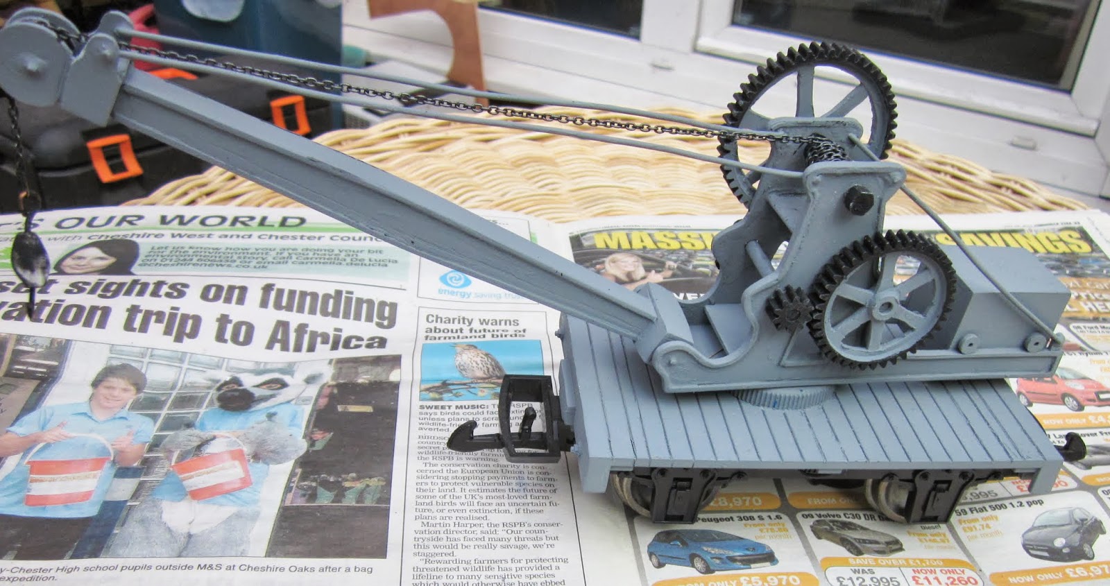
Another movement which has not occurred before was that two wagons on the Down train, the tanker for the Copper Mine, and the crane wagon for Peckforton, were also required to immediately travel back Up the line. At first, I quietly cursed my programming for not foreseeing that this could occur and I started considering ways in which I could change the algorithm to prevent this from happening again. But on reflection, it occurred to me that this operation could happen in reality, particularly with these two types of wagon. A tank wagon could easily be unloaded in under an hour and be available to run back up the line empty. Similarly, if the crane wagon was required to offload or load something from another wagon, this could easily be done then and there, releasing the wagon to return to base.
 |
| The Up pick-up goods crossing the River Gowy between Peckforton and Beeston Castle |
So for now, I am more than happy that the program occasionally throws up a freight movement which I might not otherwise have considered.
 |
| The Down pick-up goods awaiting the all clear on the approach to Beeston Castle |
To avoid undue disruption to the passengers taking the Afternoon Mixed, I have now taken to running the train on the 'wrong' road at some of the stations. This means that I can leave the coaches on one loop while shunting the wagons in and out of the siding on the other loop. I am not sure if this would have been prototypical practice, but it seems to me to be the most obvious way of causing minimal disruption to the paying public.
 |
| The late afternoon mixed departing Beeston Market Station with Hunslet 0-4-0T No. 3 Bickerton |
For me, sorting out the logistical problems of shunting are some of the greatest pleasures I derive from the hobby. I am finding that the Hunslet, No. 3,
Bickerton, is my preferred loco for the Pickup Goods and also for the Afternoon Mixed. It is the only loco which so far has been equipped with a power buffer and as a consequence it never (perhaps that's tempting fate) stumbles over dead frogs or uneven pieces of track - which makes shunting at slow speed an absolute delight. I am only hoping that I will be able to get such fine control from my radio controlled battery powered locos.
 |
| The last full ore train of the day departs the Copper Mine with the workman's coach marshalled next to the loco |
Conclusion
Believe me, there is
nothing--absolutely nothing--half so much worth doing as simply messing
about with trains. Simply messing, messing--about--with--trains.
(with apologies to Kenneth Grahame)
 |
| Early morning sunlight dapples the scene as the morning Up passengers detrain at Beeston Market |
 |
| The mid-morning Up passenger taking the bank out of Bickerton Station |
 |
| A full ore train approaching Beeston Castle with Fowler diesel mechanical No. 7 - Tollemache |
 |
| The first train of empties for the day arrives at the Copper Mine with the workmen's coach |
 |
| The mid-morning Up Passenger about to depart Bickerton Station hauled by 0-4-2T Barclay No.2 Beeston |
 I've been asked on a few occasions how I go about weathering my rolling stock. As always, I don't profess to be an expert in this field - there are some whose use of weathering powders and the like reaches the realms of artistry, but here's how I go about it. Each wagon takes about an hour to weather.