
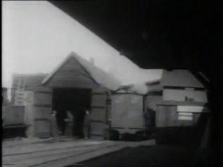
I was unable to find a photo of the engine shed in its final form but these stills from a newsreel movie shot just before the line closed give a feel for how it looked.

The shell
The shell for the shed was constructed from 5mm exterior ply. Two sides (70cm x 19cm) were marked out as were the ends (30.5cm wide x 27cm high, ie the two apexes rising 8cm above the side walls). I left marking out the roof pieces until the sides had been fitted together. I have learned from experience that it is best to measure these out to fit the actual model, particularly when the roof is more complicated than a simple apex. Windows were marked at 11cm from each end with 11cm gaps between and 5.5cm above the base. Their dimensions were dictated by the 3.7cm x 4.8cm rectangular Jackson's Miniatures windows which I had acquired previously (though these were later replaced by their arch windows, see below). The front doorways (18cm x 12cm) were cut out as was the rear doorway (4.5cm x 9cm) to match the Jackson's Miniatures doorframe. The main doorways are a tight fit for my locomotives and in hindsight I would now make these slightly wider.
The sides, ends and windows were then cut out with a powered jig-saw.

Holes were drilled in the corners of the doors and windows to allow the jigsaw blade to turn through 90 degrees.


Note that originally I was intending to model the earlier clerestory style roof, hence the apexes at the ends were sliced off. Later I decided to keep it simple and restored the apexes.

Weatherboarding
I had considered buying plastic weatherboarding overlays from Jackson's Miniatures to clad the building, but decided to use coffee stirrers to achieve a slightly more bespoke look. Firstly the verticals were fixed in place - two layers of stirrers glued in place with exterior PVA. Then began the laborious process of overlaying the horizontal planks, starting from the bottom and working upwards.
The glue was spread in a zig zag patterns to ensure that there was sufficient to fix both edges of each plank.

Initially, the planks were held in place with clamps

but higher up the walls weights were needed to keep them in place while the glue set.

Note: The windows were loosely positioned to enable the correct alignment of the planks. The door frames for the main doors were similarly made from a double layer of stirrers.

..... and the spaces in between layered with weatherboarding.

The main doors
The doors were constructed from lolly sticks. Two sticks, one 105mm and one 59mm, formed the verticals. behind these four 60mm pieces formed the horizontals; one each near the top and bottom and another two midway to coincide with the joints:

Once six verticals had been glued in place, the horizontals were checked and adjusted to ensure they were square.

and then the diagonals were marked out by eye.......

..... trimmed and glued into place.

Then the ends of the verticals were tidied up with a craft knife.

The hinges
Some 16thou brass shim was marked out, 30mm x 5mm and cut out using a pair of scissors.

Each one was then tapered slightly and rounded at one end using a file.

The blunt end was then turned up using a pair of pointed nose pliers.

The hinge was then wrapped around a piece of 1/16" diameter brass rod.......

....... using the pliers. Then four depressions were made on the back of the hinge at 5mm intervals to represent the bolts by lightly tapping a scriber.


The hinge was then glued with epoxy resin to the door.
Update (April 2012): The epoxy was unsuccessful in taking the strain and holding the the hinges to the door, as was Superglue. I have now drilled through the hinges in a couple of places and pushed shortened dress-making pins through into the wood of the door. Superglue has also been used to reinforce the join. Hopefully this should prove more effective. (See Progress Report 41)

A 5mm length of 1/16" brass rod was bent through 90 degrees with the pointed nosed pliers and then trimmed off 5mm from the bend.

Two 1.5mm holes were drilled in the door pillar into which the bent rods were inserted. The hinges were then hung on these


Before joining the ends to the sides, the ends of the planks which extended beyond the sides ......

....... were trimmed off to leave a regular 2mm overlap.

In the meantime the window spaces had been enlarged with a jigsaw to take the new replacement arch windows

The sides and ends were joined together with brass panel pins and exterior PVA, the sides fitting inside the ends to allow the slope of the roof to butt against the tops of the sides.

The four roof pieces were individually measured, marked out and cut to fit. The roof pieces were tacked and glued in place, and then sealed with silicone sealant.
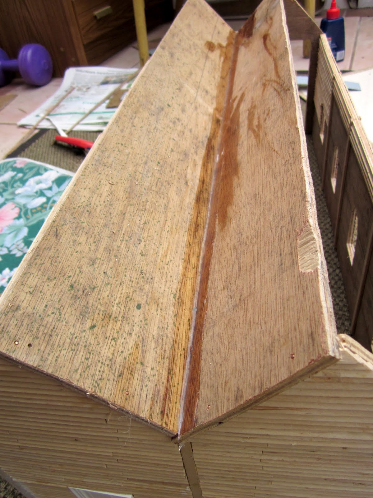
Once the walls and roof had been fixed in place, roof timbers were cut from 8mm square stripwood and glued in place to coincide with the verticals on the outside of the walls.

Painting
The outside of the building was initially painted with primer/undercoat. The verticals were picked out in two coats of Buckingham Green exterior paint and the walls in two coats of cream masonry paint.

The interior was painted matt black. I had considered leaving it white, but decided that as I was not going to detail the inside of the shed a dark interior would attract less attention.

The doors and windows were sprayed with grey primer and then given two coats of Buckingham Green.

The roof
Firstly, the sides of the roof were planed off vertically with a miniature plane.

Surplus pieces of 1cm wide uPVC trim left over from the construction of the swing bridge (see How I constructed a swing bridge) were superglued to the edges of the roof ......

..... and then trimmed off flush with the ends ......

.... to form bargeboards Further pieces of trim were marked by eye, trimmed and superglued to the eaves.

Once the glue had set, the top edges of the side bargeboards were skimmed with a craft knife to match the profile of the roof slope.

The bargeboards were then given two coats of Buckingham Green.
Four pieces 1" lengths of 3/4" square timber were cut and sanded for the roof vents/chimneys.

Slots 3/4" apart were cut into the apex of each roof, 17.5cm from the ends.

These were opened out into 3/4" holes with a craft knife.

Four pieces of 25mm x 25mm x 5mm stripwood were cut out to act as caps for the roof vents.

The vents and caps were then glued into place in the slots and painted matt black.

Four strips of Jacksons Miniatures plastic roofing sheets were cut to size and the gaps between the slates filed along the lower edges where they were to overlap the sides. I had wanted to use real miniature slates for the roof but worked out they would cost somewhere in the region of £300 so thought better of it.

Evostik 'Wet Grab' adhesive was spread over the roof surface and the sheets fixed in place.

2.5cm wide strips of Evostik flash band were cut out and scribed at 1.5cm intervals.

These were then fixed to the ridges of the roofs.

A mix of black and dark brown Acrylic paint was daubed on to the roof sheets .......

..... and wiped off with paper towels while still wet.

This was repeated across the entire roof.
All paintwork was then given a thin wash of grubby acrylics and wiped off with a paper towel to lightly weather the building and accentuate the joints in the woodwork.

The model was then positioned and tested.
As you can see, the clearances for the locos are a bit tight so the shed has to be positioned quite accurately. It needs to be embedded into the ground and further detailing still needs to be added (eg gutters, downpipes, ash pits etc.). But it fills a much-needed gap in the infrastructure of the railway.


Some views of the shed in context:


1 comment:
Marvellous. You must drink a lot of coffee to obtain that many stirrers! I need an engine shed and you have certainly given me enough ideas and technique to enable me to begin. Excellent model. Rick
Post a Comment