 Contents

Preamble
After carefully studying the drawings in Bernard Rocket's excellent book (Glyn Valley Locomotives: 16mm scale drawings, Theodore Press, 2007) and various photos of the Beyer Peacock Glyn, my next job was to figure out how to break it down into pieces which could be 3D printed. Normally, I try to ensure that, where possible, flat sided parts are printed horizontally to minimise the layering effects which are inevitable with 3D printing. However, as the bodies of the GVT tram locos have curved corners, I decided to try creating the sections of the body so they would print vertically.
3D Drawing
The body was broken down into six main sections: the skirt, the lower body,
the smokebox, the cab, the tank and boiler tops and the roof. Smaller parts
such as the smokebox door, chimney, toolbox, doorways and sandboxes were
drawn separately. I used
Tinkercad, which is my preferred 3D CAD package having tried others and, although I
mastered their main drawing techniques, I struggled to produce viable (ie
printable) parts.

As can be seen, the 'tools' in Tinkercad are basic shapes which are
reshaped and joined together. If you think about it, a steam locomotive is
basically a few cuboids and cylinder shapes bolted together.

OK, there is a bit more to it than that, but you get the general idea.
Once all the parts had been drawn and joined together virtually on-screen to
make sure they fitted together ....

.... the individual parts were exported as .STL files, imported into my slicer
program (Cura) and then transferred to my 3D printer to be printed out.
Construction
The actual construction of the loco was very straightforward. I decided to use
the motor block from a Bachmann Streetcar - because I happened to have a
couple in my bits-box. Of course, any powered chassis or motor block/bogie can
be used as the skirts hide a multitude of sins (unless you decide to construct
the model with its skirt flaps raised).
My first task was to remove the track pick-ups from the motor block as my
model would be battery powered. The block was disassembled, by removing the
six screws holding it together.


..... and the harness was then taken out completely (and put into another
bits-box - who knows when it might become useful?)


After a test-fit, I realised I needed to cut additional slots in the running
plate of the main body-part for the wheels, if the block was to sit at the
right height for the skirt. This was achieved with my trusty razor saw.


NOTE: I use thick (High Viscosity) superglue from
Tool Station
(but make sure you go through the age verification process or it won't be
delivered!)

.... and the motor block checked again to make sure the body was the correct
height above the track.


..... and nuts were screwed on. It's not often I have such an easy solution to
attaching my loco bodies to their motor blocks!

The smokebox door was then glued into place


Then I realised I needed to cut a couple of notches in the front of the tanks
behind the smokebox to clear the wheels of the motor block (if your moto block
doesn't have such large wheels then you won't need to do this).

The smokebox and front of the tanks could then be glued into place.

The tank/boiler top section was then test fitted. As I wanted this to be
removable, I glued a couple of pieces of 2mm thick plasticard to the insides
of the tanks to stop it from slipping down (just visible on the left of this
picture.

The cab was now glued into place. It took a bit of jiggling to make sure it
was sitting accurately on the body but hopefully its position is fairly easy
to figure out - it has to butt up to the tank top section so make sure this is
in place before gluing the cab.

The insert into the base of the cab roof was then glued in, making sure it was
centrally located. Note that the cut-outs are aligned with the front of the
roof (where the ventilation holes are placed) to give clearance for the cab
windows.

The access flaps were then glued into their spaces in the skirt. Note how the
step hole aligns with the door of the cab .......

..... and just forward of the door into the smokebox section. You could glue
these in the open position but that might reveal that you have no cylinders,
coupling rods or motion).

The cab door was then attached (handle to the rear) .....

.... as was the door to the smokebox section (handle to the front). These can
be glued open if you so wish - quite a few photos show these doors left open
when the locos were running.

The chimney was then glued into place.

With the body more or less complete, I turned my attention to the trailing
bogie. This is not essential as it will be hardly visible beneath the skits,
but I'll know it's there. I used a set of IP Engineering 20mm dia
wheels (again because they were in another Bits Box). The axle was placed in
the slot and the pivot piece was glued into place.


The pivot for the bogie was then bolted on using the same screws holding the
motor block into place. If you are using a different chassis or motor block
you may need to make your own arrangements (or not fit the bogie at all - it
isn't essential - and does take extra faffing when placing the loco on the
track).

A self-tapping screw was used as a pivot.

After gluing the toolbox on the the right hand side of the tank top, just
ahead of the filler, the loco was now in a state to be test-run. A temporary
battery pack was fitted and wired-up with a make-do on-off switch.


Holes were marked and drilled for M3 screws to hold the block in place ....


Finishing and painting
The main disadvantage of printing items vertically is the clearly visible
striations which mar an otherwise smooth surface. I noticed that additional
ripples seemed to emanate from the rivet heads.

These undulations required a
fair bit of rubbing-down and some filling with Squadron White Putty in order to get a reasonably
smooth finish. The body was then given a couple of coats of primer (Halford's
grey) from a rattle can aerosol before being rubbed down again and at least three coats of Halford's
satin black were applied.

The backhead was also painted black with detailed picked out on gold, copper
and red. NOTE: This was printed on my cheaper lower quality printer which is
why the finish is not as smooth.

Nameplates were drawn in Tinkercad and printed out using a resin
printer to provide finer detail.


 Buffers and my own less obtrusive LGB style hook and loop couplings were added
so the loco was now ready for some serious test running.
Buffers and my own less obtrusive LGB style hook and loop couplings were added
so the loco was now ready for some serious test running.


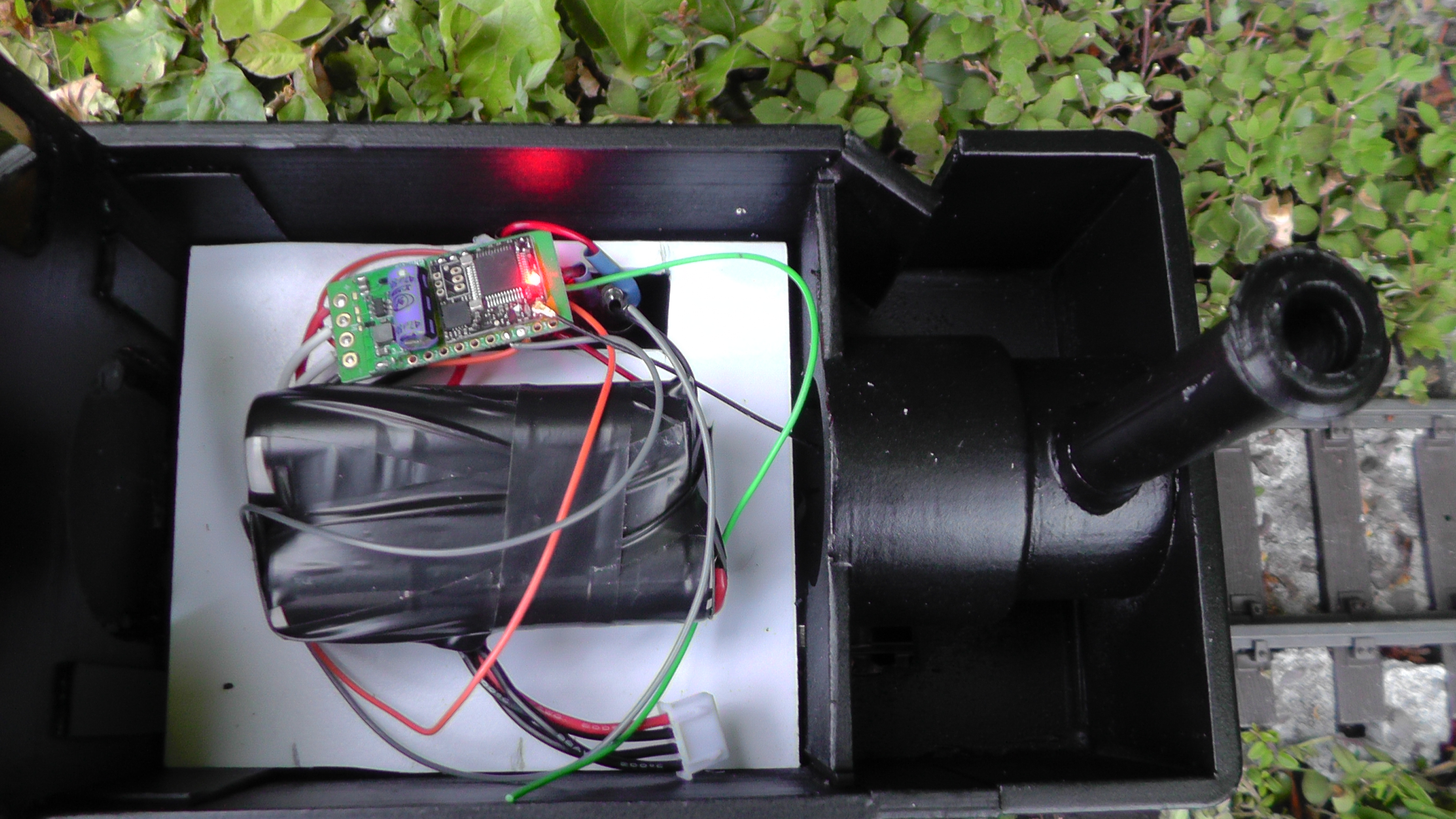
Wiring
I used my tried-and tested approach to wiring up the loco.

Three 18650 li-ion cells with tags (from
Ecolux) were wired-up through a 3S battery protection board to act as a
power-source.
Holes were drilled through the running plate for the charge socket and
switch ......

..... and then everything was wired-up to a
Micron MR603a receiver/controller. This is compatible with
Deltang equipment which enables me to continue using my
Deltang transmitters which, until now, have been my go-to radio
control system ( see
Getting started with Deltang).
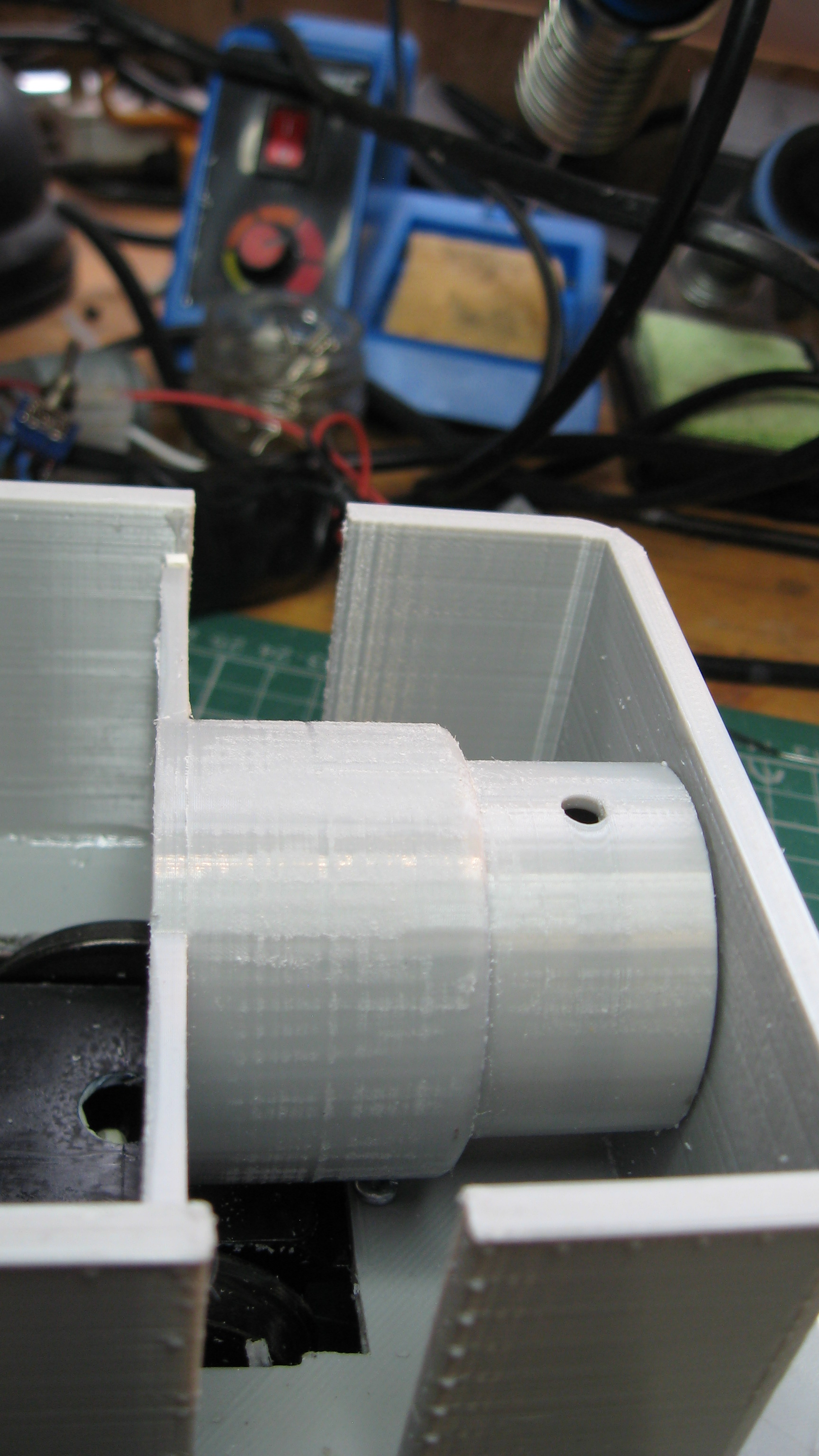
The floor of the tanks section was raised 7mm using an offcut of PVC
foamboard, to provide clearance for the top of the motor block and wheels.


The loco could now be tested more thoroughly.
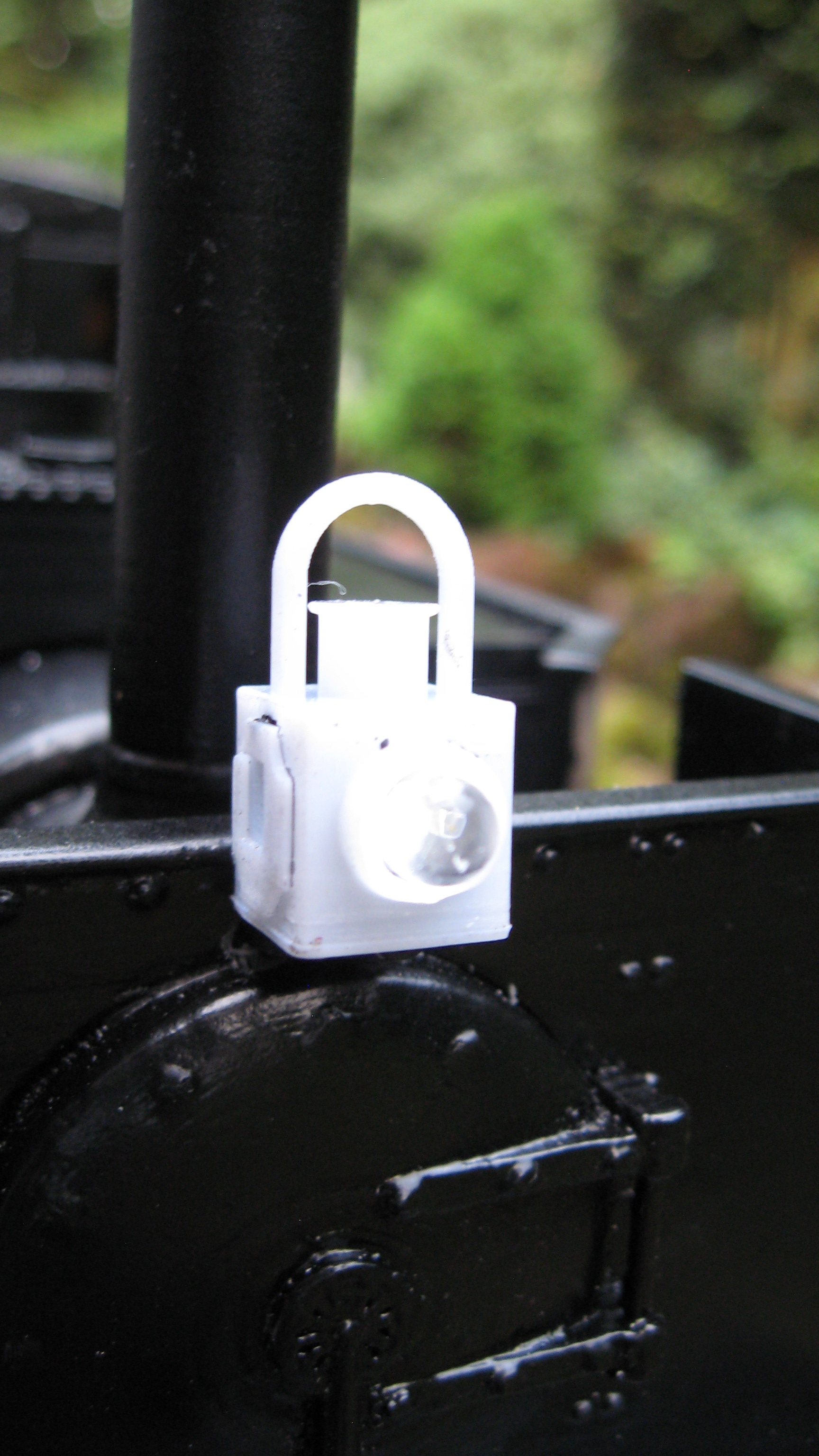
Satisfied that all seemed well, I added 3D printed loco lamps to the front
and rear, fitted with 5mm bi-colour red/white LEDs. These were wired-up to
output pads 1 and 2 on the MR603 to provide directional lighting.
which changes colour dependent on whether the loco runs forwards or in
reverse.


I also added a MyLocoSound British Steam soundcard - wired up as
below. The trigger for the whistle on the soundcard was connected to output
pad C on the MR603. The speaker was mounted in the roof of the cab
which is where I usually place them as it allows the sound to escape, it is
fairly unobtrusive and easily accessible.


Conclusion
The GVT Beyer Peacock loco seems to me to be a really good choice for
someone wanting to try their hand at creating a battery powered steam
outline loco to run on their railway. The cavernous body provides plenty of
room for batteries, radio control equipment and a soundcard. The skirts mean
that any sort of 45mm or 32mm gauge powered chassis or motor block could be
used,
I have, however, been finding that the Bachmann streetcar motor block I have
used is somewhat under-powered when compared with my other locos which use
LGB motor blocks. Presumably, streetcars don't really need to be powerful as
they usually tow nothing more than a single trailer. I might experiment with
using a different motor block - I do have a slightly larger wheelbase USAt
block in the Bits Box - or alternatively, I might even explore constructing
my own chassis.
However, in the meantime, I am enjoying watching an all-black loco chuffing
around the garden.
Downloads
All the .STL files for the loco can be downloaded from the gardenrails.org forum
- https://gardenrails.org/forum/viewtopic.php?f=55&t=13995
NOTE: You will need to register with the forum to access the 3D files download section where there are a large number of rolling stock and lineside accessories available for free download.
There is no registration fee for the forum but if you feel you would like to make a contribution to its upkeep and running then there is a link to the forum's PayPal account in the introduction to the 3D print files section

14 comments:
Thanks for another great update and a wonderful blog, finding it was the reason I started my garden railway journey and I'm loving every minute of it. I've been tinkering with filament 3D printing for 10 years now and 2 things I've found may help. The additional ripples that emanate from the rivet heads, these are always going to be an issue and and due to the structure of the printer moving due to the high directional accelerations involved. I've found it's always best to reduce the maximum accelerations and maybe the velocities to make these much smaller as a longer print time is better than lots of sanding time. Also dowels are your friend with a 3D printer, I use them to connect most parts. For the dowel material I use 1.75 filament and superglued in one hole and along the edges, this gives a strong bond and positional alignment when 2 to 3 are used between parts. Keep up the great work and I'm looking forward to the next update.
Thanks Jim
Two really helpful ideas. I'll give them both a try.
Rik
Rik..will be printing your loco for my On30 line, thanks very much for posting all the parts, just one question , where is the backhead detail, I can't find it. Doug
Hi Doug
Good question. Not sure of the answer. I can't remember whether I did a backhead for the 0 scale version. I'll take a look on TinkerCAD and let you know.
Rik
Just checked TinkerCAD and it looks like I didn't do a backhead for the 7mm scale version. I'll see if I can shrink the 15mm scale one down. It might work or it could end up making a mess of the detailing.
Rik
Thanks Rik. If you have a problem just post the STL and i'll try at my end.
thanks again for the great work.
Doug
Hi Doug
I've now posted the backhead section on Thingiverse. I've no idea how or if it will print successfully. If not, get back to me and I'll try tweaking it a bit
Rik
Hi Rik
I'm now in the final print stage, so far so good, the more of this model that's revealed the more impressed I get with the details. Some minor fettling was required but that due to resin shrinkage, other than that it fits together quite well. I will post a picture when I have some paint on it.
thanks
Doug
Thanks Doug. Will be interested in seeing the end result. I hope the backhead turned out ok.
Rik
Rik here is a lineside shed that I designed, it might fit on your Railway when rescaled.
https://www.thingiverse.com/thing:5577666
Interesting. How did you draw the corrugated roof?
Each side of the roof is a flat slightly thicker than the corrugation, i then side cut the corrugation pattern into the edge, married 2 roof pieces and the fitted the cap. The original was made from multi layers of card, blended it all into one part and fitted the new roof ASSY.
The little under eve was draw in after that. Saved it all as an STL and there it is.
I liked the lamp idea you used so i drew up a similar design to On30 and fitted 2 102 SMD LED's, one red one white, joined in opposing polarity so that reversing the polarity of the power, changes the colour.(i am using an arduino and a HC12 as a home made controller) I was using Micron TX22 but when the supply problem happened i had to make an alternative, i still have a few Micron controllers and receivers left. But will provably no longer use them. Shame they are quite good but i have changed over now.
How do you find the HC12? Does it work reliably?
I tried using a NRF24 but gave up because I couldn't get it to work reliably. By contrast, the HC05 was great but I don't like using a mobile phone as a transmitter. I can't see the screen when the sun shines.
I am thinking of using a HC05 as a master inside a transmitter but not got around to Tring it yet (too busy 3D printing)
Post a Comment