
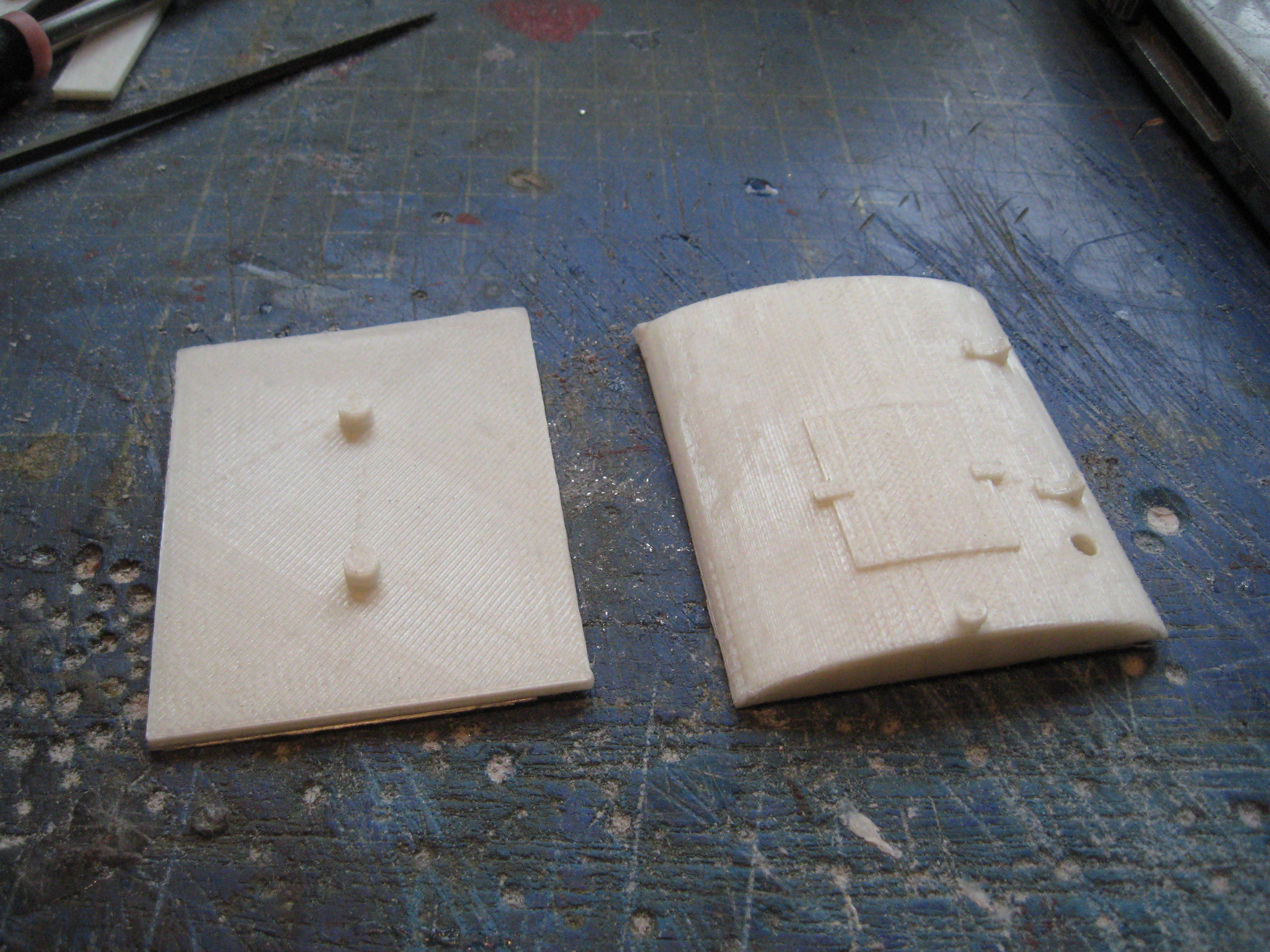
The parts for both the original loco and the variant were downloaded and printed out. They were cleverly drawn so that for most of the parts, no additional supports were needed, apart from the cab roof and the handrails. I eventually gave up on the hand rails as I decided they were very fragile and I decided they could easily be made from brass rod.
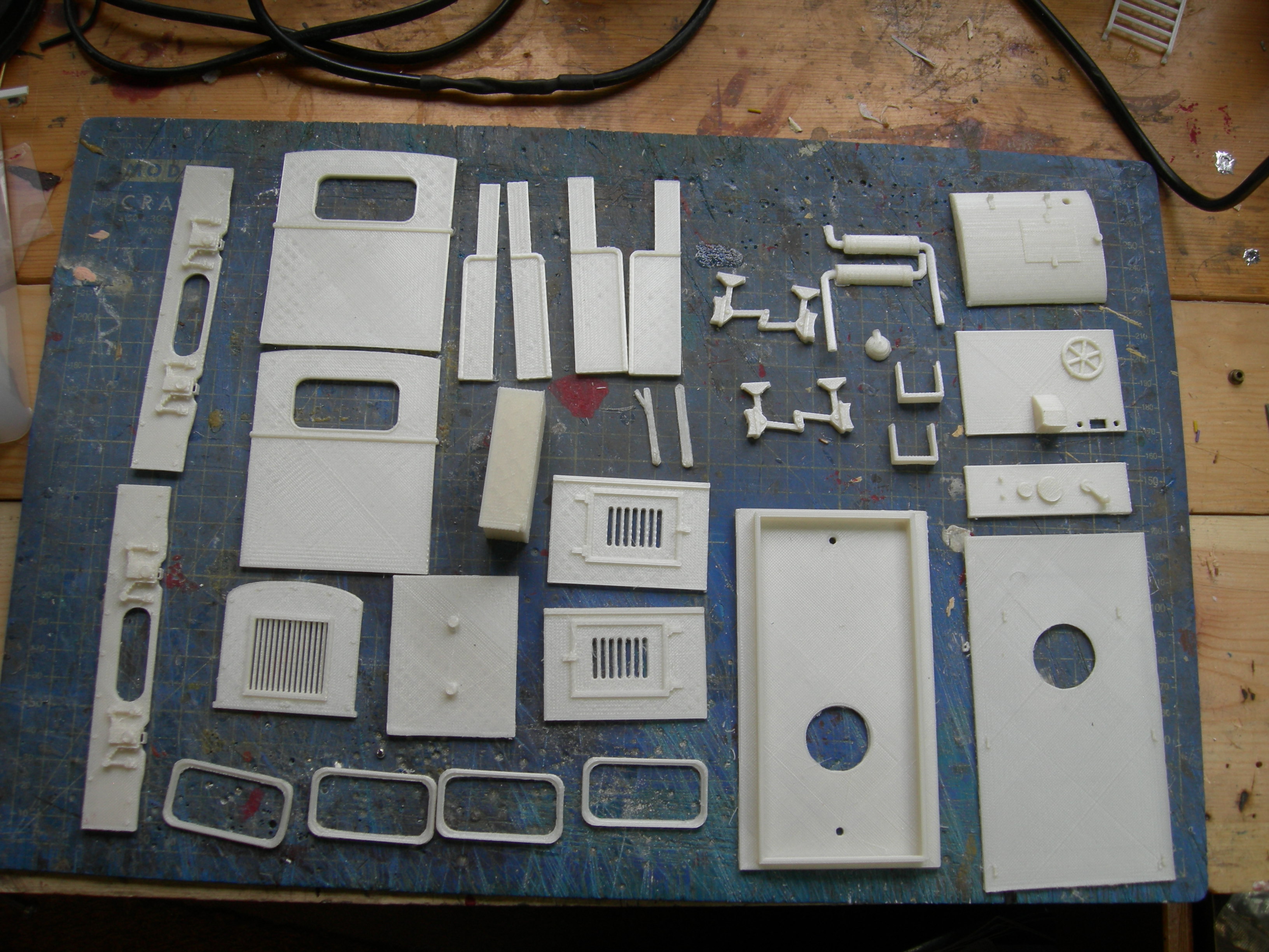
A .pdf document describing the construction process as also downloaded and I used this to guide the assembly of the parts.
The underframe was constructed first ......


20 mm diameter wheels and axles were bought from IP Engineering as was a small motor and some gears. These were put together using the relevant holes in the chassis frame.

From past experience, I have learned that the pulling power of such a chassis is greatly enhanced if Delrin 8-tooth sprockets and chain are added. These were purchased from MotionCo and, after a bit of fiddling, fitted to the chassis.


The charge socket was positioned between the wheels on one side of the loco.

The wiring for this loco follows my usual pattern, the only difference being that I replaced the toggle switch with a slide switch:


The underframe and cab interior were then masked .........

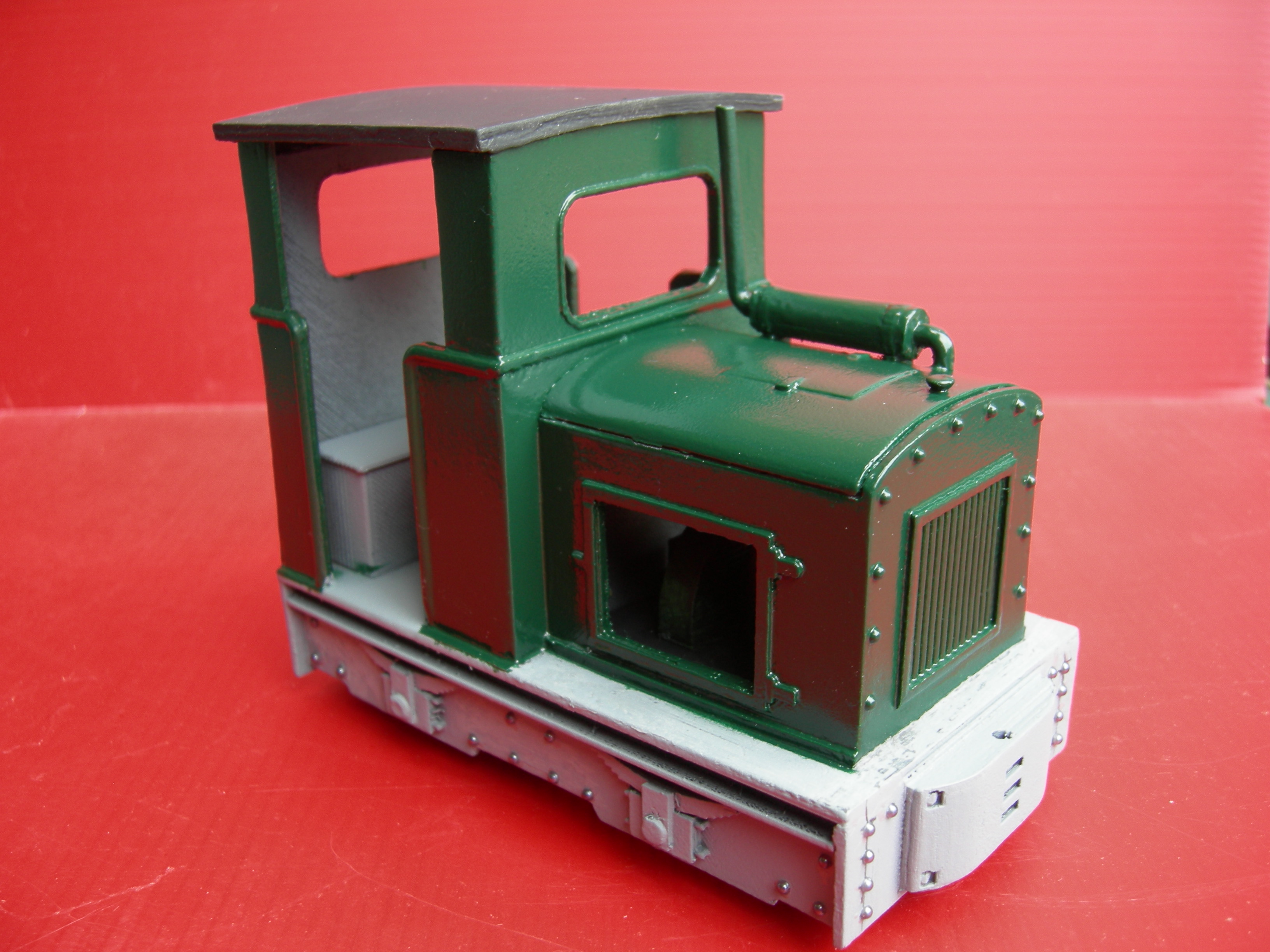
The underframe was then brush-painted with black acrylics and the buffer beams picked out in red,
Various details were now added, such as the windows......


I then decided to install couplings and buffers so they could be used with my rolling stock. As the buffer for the stock on my railway is higher than the buffer-beams on the locos, I created some risers for the buffer beams from plasticard .......


..... and more test running was carried out.

At first, only one loco was powered but it soon became apparent that, to cope with the 1:40 gradients on my railway, both would need to have motors installed, and so the second loco was duly equipped - with its motor connected to the output from the Deltang Rx65b.

In addition, name and number plates were designed in TinkerCAD and 3D printed.

The diesels have entered service and do stirling work on the Copper or and Sand Quarry trains.
Conclusion
Since constructing these diesels, I have gone on to designing my own locos in TinkerCAD and printing them out - see for example, How I constructed a Schull and Skibbereen Nasmyth and Wilson loco. One of the things I have learned from constructing these little diesels is to ensure that the loco is broken down into a series of parts which are simple to print, with no (or the bare minimum) of support structures needed.
I have not, as yet, started producing my own powered chassis - I generally use motor blocks from ready-to-run locos. But my next project will be to design, draw and 3D print a complete loco from scratch.

No comments:
Post a Comment