Several years ago, I spotted an unboxed new LGB ToyTrain diesel loco for sale on eBay at a reasonable price and so snapped it up. Even if I just used its motor block as a spare, it would be worthwhile. Quite a few of my semi-scratchbuilds are based on the ubiquitous LGB ToyTrain motor block.

Once I had finalised the radio control system in the loco, I was faced with a dilemma. Do I completely rebuild the loco into something more appropriate or just modify it, so I could continue using its modular construction for future test-bed projects?
I decided to see what a modification might look like. Although I have constructed several locos over the years, none of them has been a simple bash from an off-the-shelf model. This would be a new experience for me.
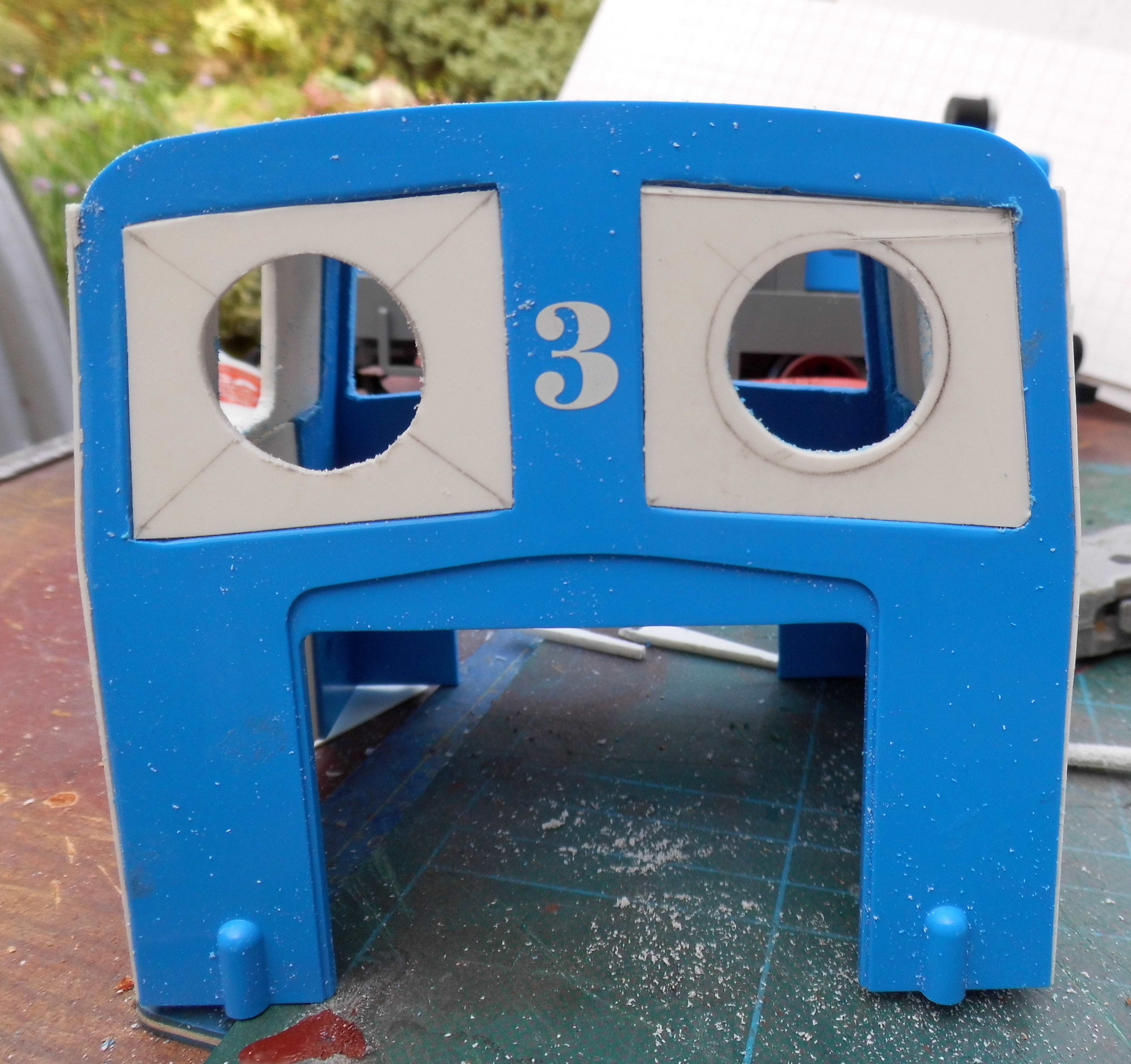
As I wanted to keep the three main body components intact (the front bonnet, the cab and the rear bonnet), I started with the cab, as I felt this would need the most modification. I decided the large square windows needed to be replaced with smaller spectacles.


..... and then marked in the centre .....


The steps were tackled next.

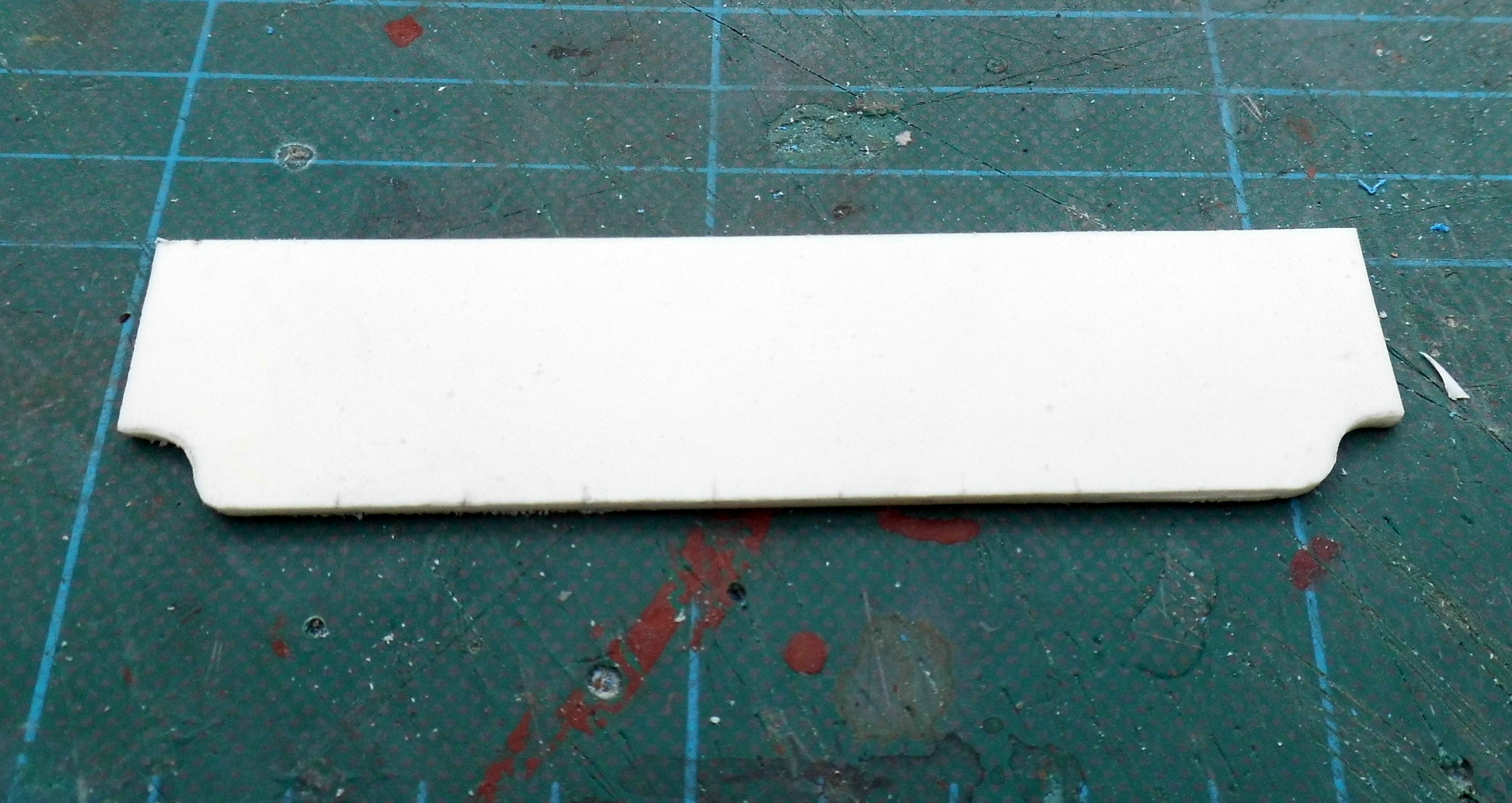
2mm thick plasticard was cut to widen the middle step and provide infill for the top step.


The sides of the cab were closed-in with a sheet of 1.5mm thick plasticard cut to size. A window was cut.....

..... and a doorway incised into its middle.

The grille at the front of the bonnet ......

.... was removed by initially drilling some pilot holes and then using a razor saw.

A new grille was made from a frame of plasticard, .......

...... infilled with a piece of metal louvre for a flyscreen supplied by an Australian fellow garden railway modeller friend.

Buffer beams were cut from 2mm thick plasticard......
...... and glued to the front and rear of the running plate.

The sub-frame of the loco was then given a couple of coats of Halfords' grey primer from an aerosol rattle can.

Similarly, the body-parts were given a couple of coats of grey primer from a Halfords' aerosol rattle can.


Once the primer had dried off, 1.5mm diameter half-round nail art gems were carefully applied to the body using dabs of superglue applied with a cocktail stick, to simulate rivet heads.

The body parts were then given another couple of coats of grey primer.

The body was given a couple of coats of Rover Brooklands Green from a rattle can and the running plate and sub-frame given a couple of coats of Satin Black.


I decided to add a layshaft and fly-cranks to the loco. Whitemetal mouldings of fly-cranks were acquired from Garden Railway Specialists.

However, their pitch (ie the distance between the axle hole and the crank pin) did not match that of the loco wheels and so, the moulding was carefully cut to separate the crank pin.

The two parts were then soldered back together, 3mm further apart, using low-melt solder. The parts were held in place with a simple jig - basically, two holes drilled in a piece of plywood; a large hole for the axle and a small hole with a brass pin inserted to hold the crank-pin in place.


Once I was sure the solder had hardened .......

...... the joint was tidied-up with a file.

A bracket for the layshaft was cut from a piece of 1.5mm thick brass and drilled along its centre line with 3.5mm diameter holes


..... and attached to the motor block with self-tap screws.

A new connecting rod was cut from 1.5mm thick brass sheet.


Fibre tap washers of the correct diameter, .......


Handrails (from bent brass rod) were attached ........

........ as were an exhaust pipe with silencer and an air intake (whitemetal mouldings from GRS).

The loco was then given some extensive testing.

Although it is an ugly looking beast, I have decided that it could have been something which served in the trenches in the First World War. It certainly has a very utilitarian air. The tractor sound effects (downloaded from the internet) seem quite appropriate for this loco and so it has now formally joined the railway's motive power roster - as loco number 20 with the name Robert.


No comments:
Post a Comment