With over six years' experience under my belt, I have now reached that point where, if I was to start all over again I would be more likely to know what to do - with the precise science of hindsight! I well remember, when I first started, I scoured the Internet for information about how to build a garden railway and bought all the books and videos I could find (See Where did I get my ideas from). This posting is to repay all the decent advice I gathered and to offer a few suggestions of my own based on experience. As with all my postings, I do not profess to be an expert, but I hope my jottings may be useful for someone else setting out on this adventure.
This posting is divided into 9 sections:
I've made a couple of videos summarising the process of building my railway which you might find interesting - the first is short and focused while the second is longer and provides more detail.
I spent ages (literally years) planning my railway. As you can see from my early scribblings, I toyed with all sorts of ideas until eventually hitting on the design which seemed the most promising (See Planning the Railway or How to plan a garden railway )

Once I hit on the basic layout, I thought of ways in which it could one day be extended. Then split this into different phases, so what once I did the initial landscaping, I would have in mind what might happen next.
This posting is divided into 9 sections:
- Planning the line
- Landscaping
- Preparing the trackbed
- Choosing and laying the track
- Plants
- Power
- Rolling stock
- Detailing
- Operation
I've made a couple of videos summarising the process of building my railway which you might find interesting - the first is short and focused while the second is longer and provides more detail.
I spent ages (literally years) planning my railway. As you can see from my early scribblings, I toyed with all sorts of ideas until eventually hitting on the design which seemed the most promising (See Planning the Railway or How to plan a garden railway )
Once I hit on the basic layout, I thought of ways in which it could one day be extended. Then split this into different phases, so what once I did the initial landscaping, I would have in mind what might happen next.
What have I learned?
- Visit other peoples' garden railways (eg Bekonscot) and see what others have done by viewing DVDs (eg Garden Railway Magic etc.)
- Read as much as you can about garden railway modelling and learn from others' experience.
- Brainstorm as many ideas as possible, before picking the one which seems most promising
- Include at least one continuous run of some sort, so a train can be left to run around a circuit whilst doing the gardening or having a barbecue
- Don't be too over ambitious in the early stages, but plan in possible extensions to keep interest going as more funds become available
- Decide on a prototype area or region, to help focus the sort of stock to be purchased (and avoid investing in things which are inappropriate)
- Phone up or visit the main stockists (ie Garden Railway Specialists, Glendale Junction, Kent Garden Railways, Scottish Garden Railways) to find out what second hand bargains they have in stock. I bought a job lot of secondhand track from one supplier for quite a bit less than it would have cost on eBay!
- Consider joining one of the Garden Railway Associations to make contact with other like-minded modellers - eg Association of 16mm Narrow Gauge Modellers - G Scale Society
It is not necessary to make changes to the design of your garden to be able to accommodate a railway, but sometimes it is worth considering.
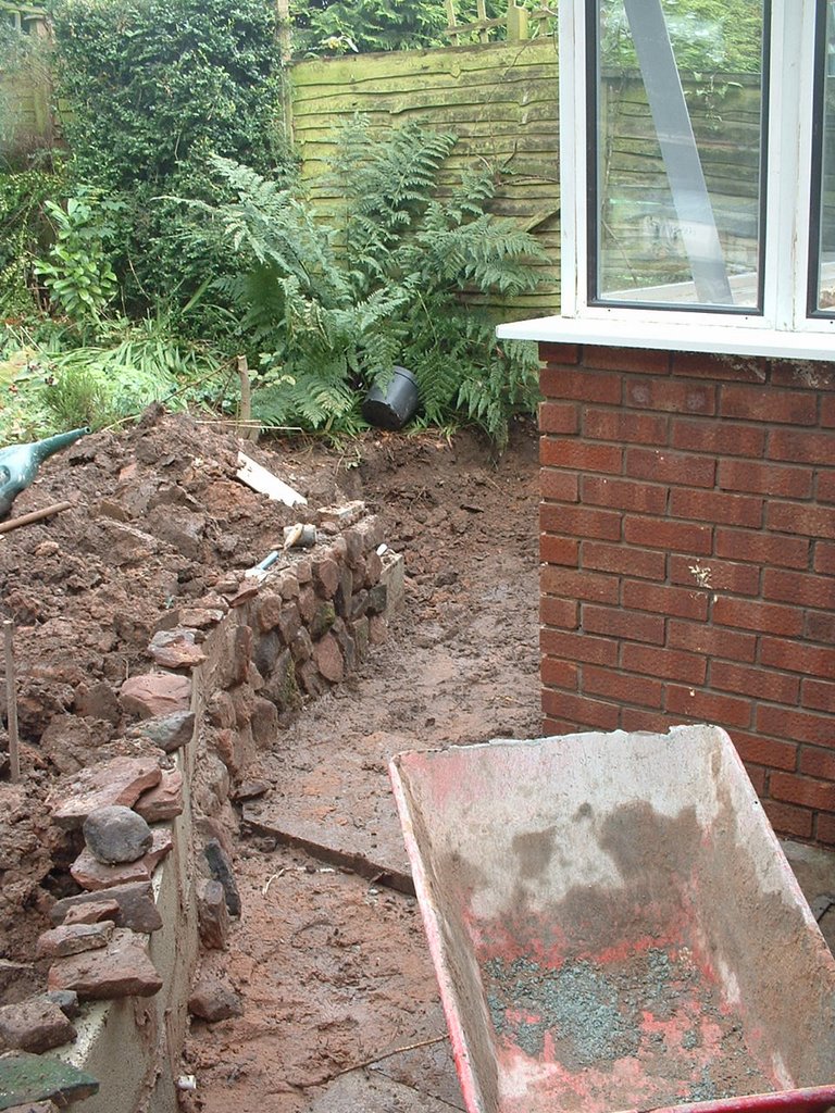
I decided to go for a wholesale reorganisation of the garden to accommodate my looped-eight design. This involved wheel-barrowing somewhere in the region of two tonnes of earth and manhandling around three tonnes of sandstone in one of the wettest summers since records began. However, the resulting railway is a lot more interesting than the original garden design would have accommodated. I was determined to include a water feature, and opted for a method of construction which was very much trial and error (see How I constructed the stream). However, I am very pleased with the results.
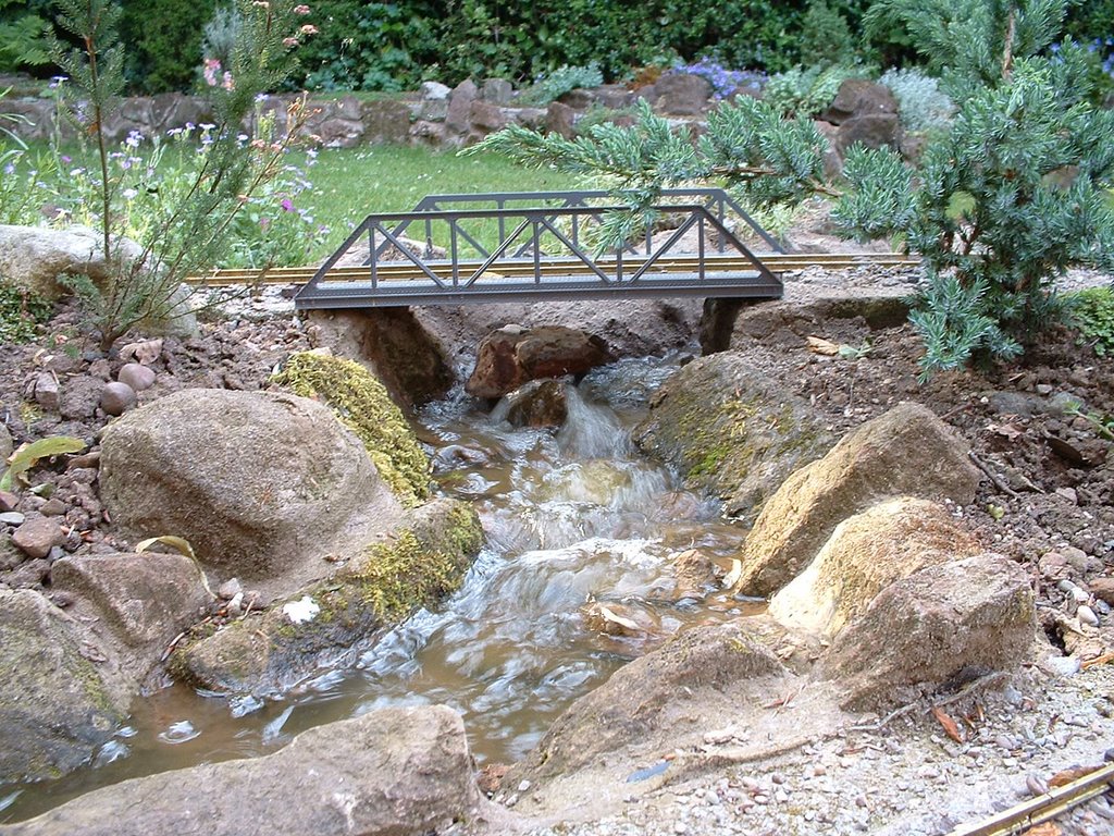
I decided to go for a wholesale reorganisation of the garden to accommodate my looped-eight design. This involved wheel-barrowing somewhere in the region of two tonnes of earth and manhandling around three tonnes of sandstone in one of the wettest summers since records began. However, the resulting railway is a lot more interesting than the original garden design would have accommodated. I was determined to include a water feature, and opted for a method of construction which was very much trial and error (see How I constructed the stream). However, I am very pleased with the results.
What have I learned?
- Putting the layout on raised beds has definitely been worthwhile. Although there is some stooping involved, much of the maintenance and operating can be done in a standing position. I'd say the minimum height for comfortable operation is 30cm (12") and 60cm (24") is quite comfortable. And, of course, when I become old and decrepit, I will probably appreciate it even more
- I did toy with the idea of hiring a mini digger, but the cost of £120+ a day seemed excessive. However, in hindsight it would have saved a lot of time and effort, and probably saved my knee ligaments from the damage caused by jumping up and down on the spade.
- I wish I'd bought more rock. Two tonnes plus what I dug out of the garden seemed like an enormous quantity at the time, but it soon disappeared. I have considered moulding rocks from concrete (eg see Making concrete rocks and cliffs), but a friend donated a trailer load from a defunct rockery he was dismantling.
- Try to keep the line as level as possible using a spirit level or laser level, but if gradients are required, then keep these as shallow as possible (see How I laid the track and Making the Grade)
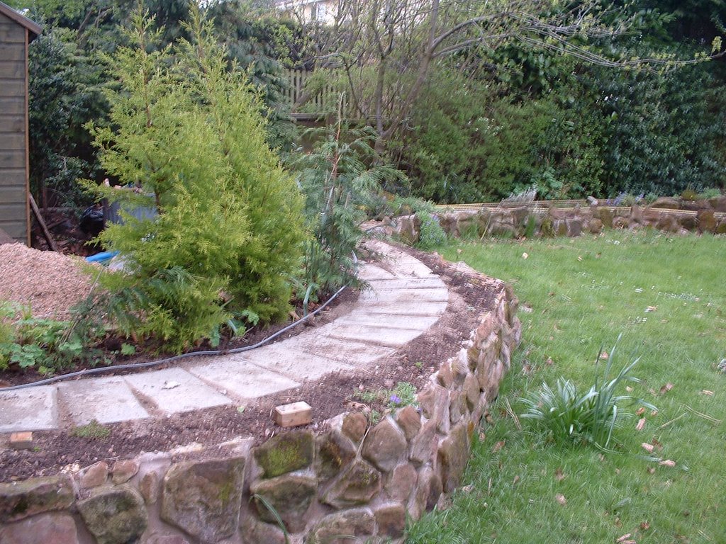 I laid my track on concrete blocks (See How I laid the track). I decided this was likely to be more flexible than shuttered concrete, particularly if ever I wanted to change the layout of the line and as I had some 'breeze blocks' left over from constructing a lean-to. For some of the line, the track has been mounted on wooden fence rails and posts (See How I constructed the extension). I had some of these left over after removing a fence along the side of the garden and hence, initially, this cost me nothing.
Other types of track foundations
Concrete
A trench is dug and/or shuttering is made defining the route of the railway and concrete is poured in. Once set, the track is glued, screwed or simply placed on the foundations. |
| Source: http://www.forum.gscalecentral.net/download.axd?file=0;221135&where=msg |
A trench is dug, lined with some sort of weed barrier fabric and filled with layers of gravel. Pre-formed track sections are laid on top of the uppermost layer of gravel. Sometimes lawn-edging is used to line the trench to keep things neat and tidy.
 |
| Source: http://i25.tinypic.com/xo2xeh.jpg |
Wood
Wood (these days mostly decking planks) are laid on the ground and track is glued or screwed to it. Soil is piled up to the top of the planks and ballast is laid loosely (or glued) between the sleepers to disguise the trackbed. |
| Source: http://ovgrs.editme.com/files/Lily/LillyN.jpg |
What have I learned?
- If using blocks or a concrete foundation then firm up the foundations beneath the blocks and spend plenty of time levelling them (using a spirit level). I use a mixture of sand and soil on which to bed the blocks. I could have laid a bed of cement for an even firmer foundation but I prefer to retain the flexibility for times when I change my plans.
- Fill the gaps between the blocks with cement to prevent weed growth. I stuffed wet cement into the gaps with rubber-gloved fingers and a small trowel.
- I used paving slabs for the base of Bickerton Station, largely because I had a couple available and because I wanted storage beneath. Although drilling holes for the rawlplugs was difficult (I blunted three masonry drill bits), the firm foundation has proven to be highly effective for the pointwork, unlike other stations where it has been difficult to keep the pointwork level apart from through the use of fillets of roofing felt.
- I have used roofing felt between the track and the wooden fence rails for the most recent sections of raised track but not on the original sections. It's too early to say if the sections protected by the felt are going to last longer but logic would suggest they will.
I decided from the start that I would use G Scale or 45mm gauge track. This was because, at the time, I had a fairly onerous job and I wanted to be able to run trains fairly quickly by buying ready made locomotives and rolling stock. Also, I knew I would not be able to afford live steam locomotives and felt more confident with using track power as I had spent most of my life modelling indoor railways. I am also very interested in narrow gauge railways and there are plenty of models and kits available in 16mm scale - which would mean 45mm track would (nearly) represent three foot gauge.
Other choices I could have made include:
I've used five different types of brass track quite successfully together - LGB, Aristocraft, Piko, Trainline and Tenmille.

My initial choice was Tenmille, as I intended to use their larger radius points throughout - which were cheaper than the LGB equivalents. Unfortunately, I was unable to buy their pointwork and so had to go for LGB. At first, I used the special Tenmille to LGB rail joiners, but more recently have found that standard LGB rail joiners (with the tab removed) to be fine. The Aristocraft rails appear to be cast from a different sort of brass to LGB and Tenmille which is softer (hence more inclined to kink when bent) but tarnishes less easily - and hence takes less effort to clean.
Other choices I could have made include:
- 32mm track, 7mm : 1foot scale (1:43) - standard gauge models (0 scale)
- 32mm track, 16mm: 1 foot scale - 2' narrow guage (SM32)
- 32mm track, 7/8" : 1 foot scale - 18" narrow gauge (7/8" scale or SE32)
- 45mm track, 10mm : 1 foot scale - standard gauge (Gauge 1)
- 45mm track, 13.7mm : 1 foot scale (1:22.5) - metre gauge (G scale)
- 45mm track, 15mm : 1 foot scale (1:20.3) 3' narrow gauge (Fn3)
- 45mm track, 7/8" : 1 foot scale (1:13.7) - 24"gauge (7/8" scale or SE45)
I've used five different types of brass track quite successfully together - LGB, Aristocraft, Piko, Trainline and Tenmille.

My initial choice was Tenmille, as I intended to use their larger radius points throughout - which were cheaper than the LGB equivalents. Unfortunately, I was unable to buy their pointwork and so had to go for LGB. At first, I used the special Tenmille to LGB rail joiners, but more recently have found that standard LGB rail joiners (with the tab removed) to be fine. The Aristocraft rails appear to be cast from a different sort of brass to LGB and Tenmille which is softer (hence more inclined to kink when bent) but tarnishes less easily - and hence takes less effort to clean.
I was disappointed with the Aristocraft pointwork, which seems to use steel screws rather than brass or stainless steel. Hence the screws rust very quickly. Otherwise, they perform the job just as well as LGB (and are cheaper). The point motors for Aristo need an AC input, whereas the LGB need DC - hence the two are incompatible if you are intending to have your pointwork electrically operated. Since I started building the railway, I have also used pointwork from Piko and from Trainline45 and found them to be equally compatible.
Coming from an 009 and 00 gauge background, I prefer to use flexible track, which can be shaped to fit the location, rather than the other way round. I've not really experienced any problems with laying flexible track in the garden, except on one occasion when I had a rail joint in the middle of a fairly tight curve.

This was quickly remedied by replacing the faulty section with a new length of rail (See Progress Report 15)
I've bonded all the joints with soldered 'jumper' leads (See How I bonded the rails). I found this needs a hefty 75 watt soldering iron as a weedy 25 watt iron doesn't pack out enough heat. I understand gas-powered irons can be effective and highly portable but have never tried one.
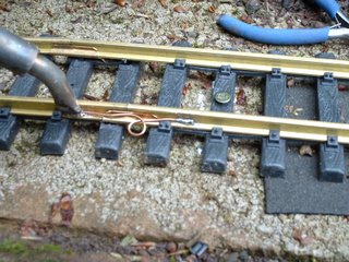
One reason why I opted for flexible track was to cut down the number of rail joints needing to be bonded - it can be a time-consuming process but to my mind, well worth it. I understand that some opt for graphite grease in the rail joiners to assist with electrical continuity and/or use rail clamps which are clearly a more expensive solution than soldering but are less fiddly and make lifting track easier should track formations need to be altered.
 |
| Source: http://www.svrronline.com/images/100_1907.jpg |
What have I learned?
- I decided very early that I wanted to model a narrow gauge railway on 45mm track and focused my purchasing around this decision.
- It's OK to mix track types - LGB rail joiners are fine for all combinations of track
- Aristo track takes less effort to clean than LGB or Tenmille
- Flexible track needs to be fixed in place quite firmly (unless you have a rail bender - which I don't) - but try to avoid having rail joints on curves (unless you have a rail bender)
- Try to avoid fixing points down as it can distort them. Rely on the plain track either side to hold the points in place
- Bond all rail joints using a heavyweight soldering iron - but ensure the 'jumpers' allow for the expansion and contraction of the track - particularly where long flexible track sections are used

For more detailed information on my experiences see What types of plants seem to work best. (pending).
What have I learned?
- Keep looking at private an public gardens to pinch ideas. Not far from where I live is a private garden which is planted exclusively with heathers and conifers. Some of my ideas have originated here. You could always visit Bressingham Gardens in Norfolk. Plenty of ideas for gardeners with the added bonus of live steam railway exhibits.
- When visiting the garden centre, read the plant labels carefully. Look for plants with small leaves, a slow growing rate and whether they will tolerate the growing conditions in the part of the garden you are intending to place the plant.
- Keep experimenting. Nature is very good at providing you with feedback on how successful your choice of plant has been. If something becomes too vigorous, cut it back, move it or remove it. If something dies, pull it out and try something different.
Having now explored all forms of track power and converted my locos to battery power, I now know a lot more about what seems to work and what doesn't. I have not yet explored live steam - but that may be an area for future experimentation.
Track power
ProsThe great advantage of track power for someone such as me who has spent over 40 years modelling railways indoors is that it is familiar. It also provides a fairly reliable means of powering locos and, with DCC (Digital Command Control) offers a lot of flexibility - there's no need for isolating sections or complicated systems for reverse loops etc.
Cons
The two major disadvantages of track power are the need for scrupulous track cleaning and the need for supplying power into the garden through wiring. If you opt for DCC another consideration is expense - DCC systems for large scale garden railways are considerably more expensive than those for 12 volt indoor railways - decoders for each locomotive can cost upwards of £50.
Track power with remote control
For a while I ran my trains with a transformer/controller and control panel situated in an outhouse.
However, I quickly found that it's preferable to follow trains around the garden for both practical and aesthetic reasons and having to keep dashing inside whenever something needed controlling became somewhat of a chore and so I invested in an early version of the Aristocraft Train Engineer and a more powerful transformer.

Eventually, I swapped this for LGB's DCC MTS system when I found the additional wiring needed to isolate passing loops was becoming too complicated. I did consider having isolating switches mounted adjacent to each station section but the increased flexibility offered by DCC in being able to use one wireless controller to operate all the locos and the electrically operated turnouts won me over to what some in the hobby consider as 'The Dark Side'.

As you can see I have still retained an analogue controller which has to be completely isolated from the DCC system but would allow me to run trains if something dramatic happened to the DCC system.
Battery Power

Update - February 2016
In the three years since this posting was originally written, I have completely abandoned track power and converted all my locomotives to battery power with radio control. I have become so enthusiastic about the virtues of radio control that I have now set-up my own small online business making and selling transmitters and receivers based on the Deltang system - see http://rctrains.co.uk/ The comments below were made three years ago, when I was still experimenting with battery power and radio control.
Pros
- Minimal track cleaning - although the track needs to be cleared of debris and overgrowth, the rails do not need to be spotlessly shin
- If you choose the right equipment, battery power can work out to be less expensive than, or at least comparable to track power
- Provided the gearing is appropriate, locos can be made to run at very realistic slow speeds without jerking over dead sections in the track
Cons
- Some approaches to radio control can become expensive - in addition to a transmitter and receiver for each loco, a motor controller needs to be purchased which, for something reliable and realistic, can be at least as expensive as a transmitter.
- Good quality rechargeable batteries can be expensive and will ultimately need to be replaced as they deteriorate
- While some systems can be plug and play, some knowledge of basic wiring and electrics is required to make the most of radio control
- Getting started with radio control
- An introduction to the Deltang radio control system)
- RC Trains support section - http://rctrains.co.uk/Support.htm
Clockwork Power
Once this was one of the principal sources of power for large scale railways. It is surprising in today's eco- conscious world that this form of power is not still used more widely. I was first inspired to venture into the garden by reading about the Reverend Peter Denny's Trepolpen Valley Light Railway in the Railway Modeller in the 1970s and 1980s. |
Image
courtesy Railway Modeller - www.pecopublications.co.uk
|
Live Steam
I have very little first hand experience of running live steam locomotives and so I would advise you to seek advice from those who know more than me, such as:
Tag Gorton (1996) Steam in Your Garden: An introduction to live steam narrow gauge railways for the smaller garden. Atlantic Transport / Garden Rail - ISBN 0-906899-67-2
This is considered by many to be the definitive guide to garden railway live steam. Tag Gorton has been the editor of the Garden Rail magazine for many years and has had the privilege of running and test running a great number of live steam model locomotives. This is a highly practical and down to earth guide.
Suppliers of Live steam locomotives suitable for garden railways include:
- Accucraft - http://www.accucraft.uk.com/categories/live-steam/
- DJB Engineering - http://www.djbengineering.co.uk/
- Dream Steam (formerly Mamod) - http://www.dreamsteam.co.uk/mss-mamod-live-steam-garden-railway-locomotives.html
- ELR Engineering - http://www.elr-engineering.co.uk/
- Peter Angus Locomotives - http://www.peteranguslocomotives.co.uk/
- Regner - http://www.regner-dampftechnik.de/echtdampf/lokomotiven.php
- Riverdale Locomotives - http://riverdale-loco.s-nl.net/
- Roundhouse - http://www.roundhouse-eng.com/
- RWM Steam - http://www.roywoodmodels.co.uk/
7. Rolling stock
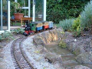

Since I started, more British ready-to-run rolling stock has come on to the market, primarily from Accucraft, and the range and quality of kits has improved markedly from such suppliers as Brandbright and IP Engineering
What have I learned?
- Before starting accumulating loads of miscellaneous rolling stock, I decided on a hypothetical location for my railway. Some modellers decide their railway will be a representation of a modern day heritage railway and use this to justify a range of stock from various period.
- I also decided from the start what type of railway I was going to model. I have certainly not regretted this as it has saved a lot of time and effort.
- Initially, I bought items of rolling stock off the shelf so I could have something up and running as soon as the track was laid. Although this stock was not appropriate for the type of railway I wanted to model, I let my imagination compensate. As time has progressed I have slowly remodelled or replaced the stock to better represent that which would be found on a rural British 3' gauge railway.
- I am happy to go for representations of stock rather than true scale models. I tend to compromise between realism and robustness. As long as it looks about right, I am happy.
- I did some research on the numbers of locos, passenger coaches and goods stock which British narrow gauge railways held (see How much stock did each narrow gauge railway have?) and then used this to help guide what I should run on my railway. As would be expected, the number of locos, carriages and the levels of each type of goods stock depended on the amount and type of traffic which was carried. For a line of my type, I reckoned on 4 locos, three coaches, and around 40 miscellaneous items of goods stock, plus two rakes of tipper wagons for the copper ore traffic (see Stock list). Any more stock and my sidings would be overloaded.
- I will probably end up with 8 locos as I want to have a roster of track powered locos and a roster of battery-powered locos to give me some flexibility. Eventually I may opt totally for battery-powered locos if they turn out to be successful.
8. Detailing
Once the hard work of landscaping and track-laying had been completed, one of the greatest pleasures comes in detailing the railway - adding those finishing touches which brings the railway to life. I am not aiming for creating a complete miniature world in my garden and prefer to see my model as a garden with a railway, rather than a model village such as Bekonscot. My focus is therefore on creating small pockets of detail, mostly around each station, although I have detailed the corner where the railway disappears behind the sheds (see Progress Report 27). Rather than creating tunnels, which would have been inappropriate for the locality in which my model is based, I have used two road bridges to mark the break between the 'seen' and the 'unseen' parts of my railway.Bridges

Platforms
There are five stations on my railway - four have cast concrete platforms (See How I cast platforms in concrete) and one is made from timber covered in roofing felt (see How I made a wooden platform).Buildings
Initially, I bought some resin kits for the station buildings (See How I constructed the station buildings) but I have also adapted a children's toy (see How I made a station building from a child's toy), used a pottery building from Stanton Abbey Pottery and scratchbuilt my own buildings from wood, clad in coffee stirrers and plastic sheeting (eg see How I made the engine shed).Signals

Vehicles
Because I have set my railway in the early 1930s, I am fairly restricted as to the model vehicles which I can buy off the shelf and so I am having to buy carefully, adapt children's toys or make my own. I have accumulated a mixture of steam-powered, petrol-driven and horse-drawn vehicles which I deploy mostly in station areas during the summer season. (see Progress Report 41 and scroll down)
People

General clutter
The accumulation of general small details to adorn station areas and the copper mine, such as benches, porters' trolleys, fire buckets, bags, cases, barrels, oil drums, crates, sacks, tools and equipment, etc. is something which is ongoing - and probably will be for ever. I pick most of these small items up at Garden Railway Fairs such as that held annually at Llanfair Caereinion, but I also make my own from odds and ends and scraps.What have I learned?
- Basically, the more detail which is added the more alive the railway becomes.
- Buildings need to be weatherproof and durable, Resin or plastic buildings are the best and these I leave out all year. Wooden buildings are more susceptible to the weather and so these are brought in during the winter and put out again in the Spring.
- Figures need to be firmly fixed down otherwise they get blown or knocked over or even stolen by jackdaws! Again, these are brought in during the winter as they usually need some re-painting. I drill a hole in on foot of a figure and insert a short piece of brass rod; the other end is inserted into a hole or small rawlplug if on a concrete platform.
- To minimise setting-up, I create small tableaux grouping figures and items together (eg outside a station building) which are mounted on plastic sheets.
- There are plenty of internet sources showing how to sculpt figures from polymer clay - it's worth learning from others with more experience.
9. Operation

What have I learned?
- Spending some time planning the layout of the railway means that I can be flexible in how I use the railway. I have a circuit for those days when I want something up and running quickly, I can run trains end to end if I want realistic practice and I have a reverse loop if I want to run trains 'out and back'.
- Using a timetable and some method of generating freight adds an extra dimension to operating sessions. Trains have a reason to be marshalled and sent to stations.
- You don't need a computer program to generate freight movements - on my indoor layouts I use cards for each item of stock and a dice to determine the destination (or whether something stays where it is).
10. The future?

Where next? One of the great things about a garden railway as that it will never be finished. In my case, because I opted for a phased approach, the line had steadily grown in length over the years. Although there is some scope for further development, I am more inclined to slowly improve what is already there. I have an ongoing ToDo list which includes construction projects as well as general maintenance (see Progress Report 41). One day I will get around to constructing the siding to the water mill and the mill itself! (Now completed, see How I Constructed the mill - December 2017). Some of my rolling stock would benefit from more detailing and every station needs further titivation. You will see above that I have now gone over fully to battery power and radio control and certainly not regretted this move - no more track cleaning!
If you are considering constructing your own garden railway then why not get started. It's surprising how quickly you can have something up and running. However, take heed - this hobby is addictive!


