After admiring the sleek lines and refined detail of the Terrier, the first task was to separate the body from the chassis.

The four screws securing the body were removed, two at the front and to at the rear .......

The chassis was then eased out from the body.


The flickering LEDs were removed from behind the firebox door.

The mounting plates were removed from alongside the motor.

The decoder blanking plate was removed from the the DCC connector.

The DCC connector ........

... was then unscrewed........

I then considered where I could place the charge socket, indicator LED. The best place seemed to be the bunker. Rather than routing the wiring through the cab, I decided to burrow underneath it.
A slot, 35mm x 10mm was marked out extending from the cut-out for the motor to the rear, reaching just inside the base of the bunker.

After removing the steps, the slot was cut out with a carborundum slitting disk in a mini drill.

Space was needed in the bunker for a miniature two-way slide switch, a 2.5mm DC socket an LED indicator LED and a three-pin JST plug.

A 39mm x `4mm rectangle of 1.5mm thick black plasticard was cut to and holes drilled and cut to accommodate the components - 7.5mm diameter for the charge socket, 6mm dia for the LED indicator, 11mm x 5.5mm for the slide switch and 3mm dia for the leads to the 3-pin JST plug.
The slide switch, LED indicator and charge socket were mounted into their holes. 3.5mm was trimmed off each of the contacts on the DC socket and a 280 ohm resistor was soldered from the negative lead on the indicator LED to the middle (-ve) contact of the DC socket.


Two pieces of 14mm x 14mm plasticard were glued to the ends of the mounting plate and a 5mm wide strip glued between them.

When the solvent adhesive had hardened, the components were wired-up to a length of 8 way ribbon cable....

The cable was then threaded into the slot between the bunker and the motor compartment and the assembly was then eased into the bunker. There was no need to fix it into place as it was a very tight push-fit.
Meanwhile four 10440 320 mAh (AAA sized) li-ion batteries were acquired from Norbert at Ecolux. These were made up by him into two solder-tagged parallel packs of two batteries.
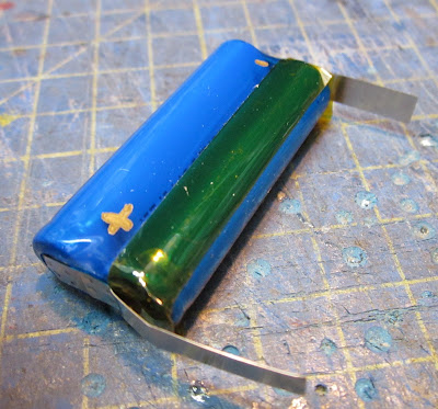
The tags were shortened and tinned with solder .........

...... before being connected to a 2S li-ion battery protection board.

The ribbon cable was then wired up to the protection board and a Deltang Rx60c receiver controller ......
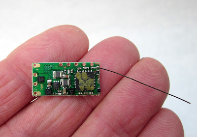
...... which in turn was connected via a 2 pin micro JST connector to the motor. The LED was connected to output Pad 1 on the Rx60, which provides a forward direction headlight and also mirrors the flashes of the receiver's LED when the receiver is not in normal use. Thus the indicator LED can show when the receiver is in bind mode (rapid flashing) or when the batteries have become depleted (the LED gives five flashes, pauses, five flashes, etc). When in normal operation the LED glows when the loco is supposed to be moving forward and extinguishes when it is supposed to be travelling in reverse. When the receiver loses or is looking for the transmitter signal the LED flashes once a second.

The loco was then reassembled. The battery packs were squeezed into the side tanks and wedged in place with 10mm squares of 2mm thick plasticard to prevent them from bearing on the flanges of the centre driving wheels. The receiver was placed inside the smokebo, making sure the wiring avoided the flywheel (there is just space!).

The loco was then tested and enjoyed.
This was a very fiddly conversion, made more difficult because of the delicate detailed features on the loco body. Some of these were removed during the conversion process and then reinstated when the conversion was completed.
The motor and loco mechanism is very smooth and so is well suited to battery power and radio control - once the problems of finding room for the batteries and the various circuitry and components had been solved.
This conversion is not for those of a nervous disposition or a faint heart. On reflection, I would have used even finer wiring than that provided by the ribbon cable. It might be possible to position the Rx60 behind the motor to leave space for a soundcard inside the smokebox. There is just room for the Rx in this space but it would have been difficult to ensure that the antenna did not make contact with the metal casting, thereby interfering with its acuity. I did consider reconnecting the firebox LEDs by connecting them to one of the output pads on the Rx, thus putting them under the control of the transmitter (eg Channel 5, bind button). However, this would have entailed even more wiring in the confined space available and so I chickened out.


The four screws securing the body were removed, two at the front and to at the rear .......

The chassis was then eased out from the body.


The flickering LEDs were removed from behind the firebox door.

The mounting plates were removed from alongside the motor.

The decoder blanking plate was removed from the the DCC connector.

The DCC connector ........

... was then unscrewed........

I then considered where I could place the charge socket, indicator LED. The best place seemed to be the bunker. Rather than routing the wiring through the cab, I decided to burrow underneath it.
A slot, 35mm x 10mm was marked out extending from the cut-out for the motor to the rear, reaching just inside the base of the bunker.

After removing the steps, the slot was cut out with a carborundum slitting disk in a mini drill.

Space was needed in the bunker for a miniature two-way slide switch, a 2.5mm DC socket an LED indicator LED and a three-pin JST plug.

A 39mm x `4mm rectangle of 1.5mm thick black plasticard was cut to and holes drilled and cut to accommodate the components - 7.5mm diameter for the charge socket, 6mm dia for the LED indicator, 11mm x 5.5mm for the slide switch and 3mm dia for the leads to the 3-pin JST plug.
The slide switch, LED indicator and charge socket were mounted into their holes. 3.5mm was trimmed off each of the contacts on the DC socket and a 280 ohm resistor was soldered from the negative lead on the indicator LED to the middle (-ve) contact of the DC socket.


Two pieces of 14mm x 14mm plasticard were glued to the ends of the mounting plate and a 5mm wide strip glued between them.

When the solvent adhesive had hardened, the components were wired-up to a length of 8 way ribbon cable....

The cable was then threaded into the slot between the bunker and the motor compartment and the assembly was then eased into the bunker. There was no need to fix it into place as it was a very tight push-fit.
Meanwhile four 10440 320 mAh (AAA sized) li-ion batteries were acquired from Norbert at Ecolux. These were made up by him into two solder-tagged parallel packs of two batteries.

The tags were shortened and tinned with solder .........

...... before being connected to a 2S li-ion battery protection board.


...... which in turn was connected via a 2 pin micro JST connector to the motor. The LED was connected to output Pad 1 on the Rx60, which provides a forward direction headlight and also mirrors the flashes of the receiver's LED when the receiver is not in normal use. Thus the indicator LED can show when the receiver is in bind mode (rapid flashing) or when the batteries have become depleted (the LED gives five flashes, pauses, five flashes, etc). When in normal operation the LED glows when the loco is supposed to be moving forward and extinguishes when it is supposed to be travelling in reverse. When the receiver loses or is looking for the transmitter signal the LED flashes once a second.

The loco was then reassembled. The battery packs were squeezed into the side tanks and wedged in place with 10mm squares of 2mm thick plasticard to prevent them from bearing on the flanges of the centre driving wheels. The receiver was placed inside the smokebo, making sure the wiring avoided the flywheel (there is just space!).

The loco was then tested and enjoyed.
This was a very fiddly conversion, made more difficult because of the delicate detailed features on the loco body. Some of these were removed during the conversion process and then reinstated when the conversion was completed.
The motor and loco mechanism is very smooth and so is well suited to battery power and radio control - once the problems of finding room for the batteries and the various circuitry and components had been solved.
This conversion is not for those of a nervous disposition or a faint heart. On reflection, I would have used even finer wiring than that provided by the ribbon cable. It might be possible to position the Rx60 behind the motor to leave space for a soundcard inside the smokebox. There is just room for the Rx in this space but it would have been difficult to ensure that the antenna did not make contact with the metal casting, thereby interfering with its acuity. I did consider reconnecting the firebox LEDs by connecting them to one of the output pads on the Rx, thus putting them under the control of the transmitter (eg Channel 5, bind button). However, this would have entailed even more wiring in the confined space available and so I chickened out.