Having completed the structure for the sawmill (see How I constructed the sawmill), I felt there needed to be some representation of the interior as the open nature of the building made the interior very prominent.

There were few, if any, of sawmills in the the UK in the 1930s and so a certain amount of modellers' licence was applied, by getting a general feel for sawmill machinery and using some common sense as to how the various bits of machinery would be arranged in the mill.
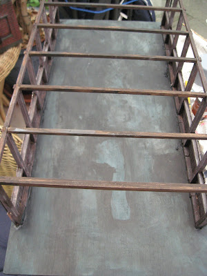
 I decided to make the carriage track and the supports for the circular saw as a single unit. I started with the carriage track.

1mm diameter holes were drilled in the longitudinal pieces at the centres of the cross-pieces and round headed brass escutcheon pins glued in place. These were for decoration rather than serving a functional purpose.

Brass panel pins were tapped in on the upper side of the longitudinal beams at each intersection of each cross-piece. These were positioned off-centre to take account of the rails which will be fixed to them.

Two 740mm lengths of code 200 rail were cut from a piece of Peco 32mm gauge track. The oxidation was removed from one side of the rail coincident with the positions of the panel pins.

The rails were then soldered to the pins.


Nine 40mm lengths of 9mm square stripwood were then glued to the underside of the track (one at each and and seven midway between the existing cross pieces), to raise it higher.
A couple of wheels from a Hotwheels model car were removed from their axle.

These were turned over......

.... and a groove filed into the tread to make them into pulley wheels.

A 5.5mm hole was drilled through the carriage track longitudinal supports at the mid-point and a 90mm long piece of 5mm dowel inserted. A K'nex bush was threaded on to the dowel (Note: the track support cross-piece was notched to accommodate the K'nex bush).

The pulley wheels were mounted on the endmost cross-pieces with a round headed brass escutcheon pin.

A length of button-thread was wound around the K'nex bush a few times and the two pulley wheels and tied together to form a loop. Three dabs of Superglue fixed the thread to the pulley wheels and bush.


A piece of 70mm x 20mm x 2mm thick plywood was cut and fixed behind one of the brackets to act as a shield.

24mm long rollers were cut from a piece of 5mm diameter dowel.

These were glued to a 135mm long piece of 6mm square stripwood which in turn was mounted on a rectangular box constructed from six 135mm long and two 6mm long pieces of 9mm square stripwood.

A couple of coffee stirrers were glued to the sides of the roller conveyor and the conveyor glued to one end of the saw housing.

Two pieces of 8mm square Plastruct tube were cut - one 90mm long and the other 28mm long. A 6mm diameter hold was drilled through the longer piece, 30mm from one end.

The shorter piece was glued to the longer piece, at the same position as the hole.

Two diagonal braces were cut from 2.5mm square section Plastruct and glued to into place.

A cap for the post was cut from a piece of 1.5mm thick plasticard and glued to the top.

The upper saw was then mounted to the bracket, using a short K'nex axle and the wheel from a cheap top as a pulley, found in my local 50p shop.

The upper saw assembly was then glued just behind the lower saw (also mounted on a K'nex axle).


..... as were eight 42mm long cross-pieces.

The longitudinal beams were notched at 72mm intervals, 5mm apart to accommodate the cross-pieces.

Wheel-mount pieces from a Lego kit were sliced in half.......


...... and the studs removed .......

...... before being glued (with Plastic Magic) to the longitudinal beams near each end at the centre.

The brackets for the log-dogs were made from three pieces of 2mm plasticard. One L-shaped (40mm x 25mm, 5mm wide), and two 25mm x 5mm pieces. A quadrant was cut into the corner of the L, using a 1p coin as a template.
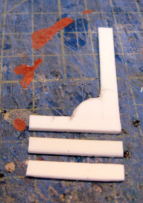
The two side-pieces were glued to the shorter leg of the L-shape and the taller leg was notched at intervals with a triangular needle file.

15mm long and 3mm wide pieces of 1.5mm plasticard were cut out and shaped for the spike and handle of the log-dog.

....... and 2mm x 3mm pieces of plasticard were also cut out ......

.... and the pieces glued to the top of the longer leg.

The cross-pieces of the carriage were then glued to one of the side-pieces ......

..... and the log-dog brackets slotted in. They were not glued, so they would be able to slide freely in between the cross-pieces.

The second side of the carriage was then glued to the cross-pieces.

Four 40mm long levers were then cut from 3mm square section plasticard. The top 5mm was filed round to make a handle and 8mm x 3mm wide pieces of 1mm thick plasticard glued to the lower ends. A 1mm diameter hole was drilled just below the handle an a length of 1mm brass rod inserted and bent as shown.

The locking levers were then glued to the quadrants of each log-dog bracket.

A suitably sized piece of branch was then test-fitted to the carriage, its Lego wheels clicked into place and the carriage mounted on the track.

Everything was then painted with acrylics. The conveyor and saw supports were given a couple of coats of a sort of olive green and the woodwork a mucky brown.


The woodwork was then dry-brushed with a lighter wood colour to highlight the wood grain.

The carriage was painted black and then rust colour dabbed here and there to show its age. Features such as the log dogs, saw blades, rail-tops and rollers were picked out in silver.


These were then glued together to make the bench, with 4mm x 4mm slats on top. I later reduced the length of the bench when trying to work out how to fit everything in the mill.


2mm thick ply was cut for the table top ......

... and to make the fence.

It was painted with acrylics to give a slightly tired and careworn look.


I did find a rather splendid mill engine whitemetal kit produced by IP Engineering, but at over £50, I felt it was more than I was prepared to pay. I had, however, picked up a model beam engine at a Swapmeet for a fiver. It had been constructed from an old Airfix kit which I think can still be picked-up if you shop around.

This is how it looked when I bought it .......

..... and this is what it looked like after I had bashed it about a bit.

As you can see, the beam and its pedestal were removed, the cylinder was placed on its side and a crosshead and slide bars added. The connecting rod was shortened (by cutting a section out of the middle and re-gluing) and then it was given a wash of mucky acrylics. No doubt, someone with more patience and dexterity would be able to make a more convincing modification but as mine was going to be tucked away inside the mill, I felt it would suffice.

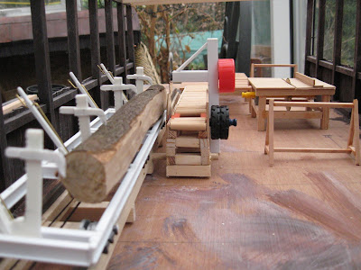
...... it wasn't until everything was completed that I could get a feel for how they would all fit together. After trying out various combinations, I decided on the following arrangement which seemed the most logical and appeared to make the most effective use of the available space.

The logs would be unloaded from the railway wagons at the top of the mill where they would be positioned on the saw carriage. Moving down, the head-saws would slice them into flitches which would be carried forward on the conveyor to the transfer bench where they would be temporarily stored. The would then be moved across to the first bench saw which would trim them to the required width and depth and thence on to the second (transverse) bench saw to be cut to length. They could then be carried out to the yard to be loaded back on to the railway trucks.
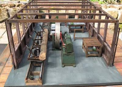
Thus, the timber would move though the mill in sequence with the minimum of effort. At first, I thought the mill looked fairly cluttered, but looking at photos of some real sawmills, mine looks quite spacious by comparison.


These were painted with red oxide paint and the rims picked out in silver.

Brackets for the layshafts were made from 10mm x 5mm pieces of 1.5mm thick plasticard to which a 5mm piece of 3mm diameter Plastruct tubing was glued, together with a couple of Cambrian Models bolt heads.

Cross-bracing from 9mm square stripwood was glued to the base of the sawmill building so the roof could remain removable.
The pulley wheels, bevel gear and cross-beams were mounted on a 210mm long piece of 3mm diameter brass rod ...

.... and this was glued between two of the main cross-beams just above the mill engine.

Another 120mm long layshaft was put together to power the second bench saw and attached to the main cross-beams connecting with the bevel gear. The belts were made from strips of thin card, painted with acrylic paints and then glued together to form appropriately sized loops around the relevant pulley wheels.

Three suitably posed figures were selected from my accumulated collection and glued in place where they seemed most appropriate.

Sawdust was glued into places where I thought it would be most likely to accumulate, though it's clear that one of the workers must be quite fastidious in sweeping up as I assume a lot more would fall when the mill was in full production.

Overall, I am pleased with the outcome. The mill has a busy, workmanlike appearance and, hopefully, will not upset too many eagle-eyed engineers or sawmill aficionados.

I need to acquire and/or prepare a few more lengths of sawn timber to arrange around the mill - most noticeably some flitches. Not sure yet how to make those as they will need to be carefully cut from appropriately sized branches and, ironically, I don't have a table saw which is capable of producing something suitable.


In the meantime, I am pleased I have managed to tick off something which has been on the to do list for several years - and fills a gap in one corner of the railway which has lain empty for far too long.


Background research
The first task was to get some idea as to what the interior of a sawmill in the 1930s might look like. I did a fair bit of research on the internet, finding a wide range of pictures - many of which were taken early in the 20th century, but mostly situated in Canada, the USA or Australia. |
| Source: http://www.discoverdarrington.com/darrington-history/darrington-ghost-towns/fortson-mill-1 |
The headsaw and log carriage
The most obvious feature of any sawmill must be the headsaw and the carriage which conveys the logs past it. My research suggested that while bandsaws were in use in the 1930s, the most common and probably cheaper option would have been a circular saw. The saw blades were my starting point - I found some likely looking candidates on eBay, intended for use with mini-drills. They were quite cheap and so I invested in a pack.
Saw carriage track
My local DIY store stocked 8' lengths of 9mm x 9mm stripwood and so this formed the basis for the track. Eight pieces 27mm long were cut, together with two 740mm long pieces. These were glued together with Supeglue, the cross-pieces being at 106mm intervals.
1mm diameter holes were drilled in the longitudinal pieces at the centres of the cross-pieces and round headed brass escutcheon pins glued in place. These were for decoration rather than serving a functional purpose.

Brass panel pins were tapped in on the upper side of the longitudinal beams at each intersection of each cross-piece. These were positioned off-centre to take account of the rails which will be fixed to them.

Two 740mm lengths of code 200 rail were cut from a piece of Peco 32mm gauge track. The oxidation was removed from one side of the rail coincident with the positions of the panel pins.

The rails were then soldered to the pins.


Nine 40mm lengths of 9mm square stripwood were then glued to the underside of the track (one at each and and seven midway between the existing cross pieces), to raise it higher.
A couple of wheels from a Hotwheels model car were removed from their axle.

These were turned over......

.... and a groove filed into the tread to make them into pulley wheels.

A 5.5mm hole was drilled through the carriage track longitudinal supports at the mid-point and a 90mm long piece of 5mm dowel inserted. A K'nex bush was threaded on to the dowel (Note: the track support cross-piece was notched to accommodate the K'nex bush).

The pulley wheels were mounted on the endmost cross-pieces with a round headed brass escutcheon pin.

A length of button-thread was wound around the K'nex bush a few times and the two pulley wheels and tied together to form a loop. Three dabs of Superglue fixed the thread to the pulley wheels and bush.

Headsaw mounting and roller conveyor
Six 60mm long pieces and six 20mm long pieces of 9mm square stripwood were cut. These were glued together to form a rectangular box. I had picked up a bag of K'nex construction toy bits and pieces at my local charity shop. Two brackets from the kit were fixed to the middle of the of the longer sides.
A piece of 70mm x 20mm x 2mm thick plywood was cut and fixed behind one of the brackets to act as a shield.

24mm long rollers were cut from a piece of 5mm diameter dowel.

These were glued to a 135mm long piece of 6mm square stripwood which in turn was mounted on a rectangular box constructed from six 135mm long and two 6mm long pieces of 9mm square stripwood.

A couple of coffee stirrers were glued to the sides of the roller conveyor and the conveyor glued to one end of the saw housing.

Two pieces of 8mm square Plastruct tube were cut - one 90mm long and the other 28mm long. A 6mm diameter hold was drilled through the longer piece, 30mm from one end.

The shorter piece was glued to the longer piece, at the same position as the hole.

Two diagonal braces were cut from 2.5mm square section Plastruct and glued to into place.

A cap for the post was cut from a piece of 1.5mm thick plasticard and glued to the top.

The upper saw was then mounted to the bracket, using a short K'nex axle and the wheel from a cheap top as a pulley, found in my local 50p shop.

The upper saw assembly was then glued just behind the lower saw (also mounted on a K'nex axle).

Saw Carriage
Two 220mm long pieces of 7.9mm Plastruct I-beam were cut .....
..... as were eight 42mm long cross-pieces.

The longitudinal beams were notched at 72mm intervals, 5mm apart to accommodate the cross-pieces.

Wheel-mount pieces from a Lego kit were sliced in half.......


...... and the studs removed .......

...... before being glued (with Plastic Magic) to the longitudinal beams near each end at the centre.

The brackets for the log-dogs were made from three pieces of 2mm plasticard. One L-shaped (40mm x 25mm, 5mm wide), and two 25mm x 5mm pieces. A quadrant was cut into the corner of the L, using a 1p coin as a template.

The two side-pieces were glued to the shorter leg of the L-shape and the taller leg was notched at intervals with a triangular needle file.

15mm long and 3mm wide pieces of 1.5mm plasticard were cut out and shaped for the spike and handle of the log-dog.

....... and 2mm x 3mm pieces of plasticard were also cut out ......

.... and the pieces glued to the top of the longer leg.

The cross-pieces of the carriage were then glued to one of the side-pieces ......

..... and the log-dog brackets slotted in. They were not glued, so they would be able to slide freely in between the cross-pieces.

The second side of the carriage was then glued to the cross-pieces.

Four 40mm long levers were then cut from 3mm square section plasticard. The top 5mm was filed round to make a handle and 8mm x 3mm wide pieces of 1mm thick plasticard glued to the lower ends. A 1mm diameter hole was drilled just below the handle an a length of 1mm brass rod inserted and bent as shown.


A suitably sized piece of branch was then test-fitted to the carriage, its Lego wheels clicked into place and the carriage mounted on the track.

Everything was then painted with acrylics. The conveyor and saw supports were given a couple of coats of a sort of olive green and the woodwork a mucky brown.


The woodwork was then dry-brushed with a lighter wood colour to highlight the wood grain.

The carriage was painted black and then rust colour dabbed here and there to show its age. Features such as the log dogs, saw blades, rail-tops and rollers were picked out in silver.

Table saws etc.
Using various online sources, I decided that I would keep things simple. Once the head-saw had split the logs into flitches (planks with bark on one or both sides), I would need one table saw to tidy up the flitches, cutting them to width, and another table saw to cut them to length. I would also need some benches or horses to support the timber while it was being sawn or waiting to be sawn.Flitch bench
Working in sequence through the sawing process, the first item was a bench to hold the flitches when they came off the conveyor from the head-saw. For the main structure, I used 6mm square section stripwood - four 20mm legs, four 30mm legs two 150mm longitudinal beams and four 70mm long transverse beams were cut.
These were then glued together to make the bench, with 4mm x 4mm slats on top. I later reduced the length of the bench when trying to work out how to fit everything in the mill.

Table saw 1
This was made from 6mm square section stripwood. Its dimensions are 70mm wide, 70mm long and 40mm high. A couple of K'nex brackets and an axle hold the saw-blade in place.
2mm thick ply was cut for the table top ......

... and to make the fence.

It was painted with acrylics to give a slightly tired and careworn look.

Saw horses
To support the timber while it was being sawn, I fabricated a couple of saw horses from 4mm square section stripwood. These are 40mm tall and 60mm wide, with 30mm wide bases.
Table saw 2
The second table saw was constructed in a similar way to the first, though slightly smaller in size (?70mm x 50mm x 40mm high). Its top surface was made from slats of 4mm square stripwood after seeing something similar in an online image.
Mill engine
I wanted my sawmill to be powered by a steam engine - I'd imagine the pace of change in our part of rural Cheshire would be slow. In the 1911 census for the district, I had come across a stationary steam engineman and a traction engine driver and felt I would like this family tradition of steam management to be continued.I did find a rather splendid mill engine whitemetal kit produced by IP Engineering, but at over £50, I felt it was more than I was prepared to pay. I had, however, picked up a model beam engine at a Swapmeet for a fiver. It had been constructed from an old Airfix kit which I think can still be picked-up if you shop around.

This is how it looked when I bought it .......

..... and this is what it looked like after I had bashed it about a bit.

As you can see, the beam and its pedestal were removed, the cylinder was placed on its side and a crosshead and slide bars added. The connecting rod was shortened (by cutting a section out of the middle and re-gluing) and then it was given a wash of mucky acrylics. No doubt, someone with more patience and dexterity would be able to make a more convincing modification but as mine was going to be tucked away inside the mill, I felt it would suffice.

Positioning everything in the mill
Although I test-fitted each piece of machinery and furniture as I constructed it, .....
...... it wasn't until everything was completed that I could get a feel for how they would all fit together. After trying out various combinations, I decided on the following arrangement which seemed the most logical and appeared to make the most effective use of the available space.

The logs would be unloaded from the railway wagons at the top of the mill where they would be positioned on the saw carriage. Moving down, the head-saws would slice them into flitches which would be carried forward on the conveyor to the transfer bench where they would be temporarily stored. The would then be moved across to the first bench saw which would trim them to the required width and depth and thence on to the second (transverse) bench saw to be cut to length. They could then be carried out to the yard to be loaded back on to the railway trucks.

Thus, the timber would move though the mill in sequence with the minimum of effort. At first, I thought the mill looked fairly cluttered, but looking at photos of some real sawmills, mine looks quite spacious by comparison.

Lay-shafts, pulley wheels and belts
After searching in vain for castings of pulley wheels appropriate for belt systems, a fellow modeller on the Garden Rails Forum offered to 3D print me some - https://gardenrails.org/forum/viewtopic.php?f=25&t=11602&start=75#p134441
These were painted with red oxide paint and the rims picked out in silver.

Brackets for the layshafts were made from 10mm x 5mm pieces of 1.5mm thick plasticard to which a 5mm piece of 3mm diameter Plastruct tubing was glued, together with a couple of Cambrian Models bolt heads.

Cross-bracing from 9mm square stripwood was glued to the base of the sawmill building so the roof could remain removable.

The pulley wheels, bevel gear and cross-beams were mounted on a 210mm long piece of 3mm diameter brass rod ...

.... and this was glued between two of the main cross-beams just above the mill engine.

Another 120mm long layshaft was put together to power the second bench saw and attached to the main cross-beams connecting with the bevel gear. The belts were made from strips of thin card, painted with acrylic paints and then glued together to form appropriately sized loops around the relevant pulley wheels.

Three suitably posed figures were selected from my accumulated collection and glued in place where they seemed most appropriate.

Sawdust was glued into places where I thought it would be most likely to accumulate, though it's clear that one of the workers must be quite fastidious in sweeping up as I assume a lot more would fall when the mill was in full production.

Overall, I am pleased with the outcome. The mill has a busy, workmanlike appearance and, hopefully, will not upset too many eagle-eyed engineers or sawmill aficionados.

I need to acquire and/or prepare a few more lengths of sawn timber to arrange around the mill - most noticeably some flitches. Not sure yet how to make those as they will need to be carefully cut from appropriately sized branches and, ironically, I don't have a table saw which is capable of producing something suitable.

I am in the process of making a gantry crane for loading and unloading railway wagons (see How I constructed a gantry crane) and will have to make a boiler-house to produce the steam needed for the mill engine (see How I constructed a boiler house for the sawmill).

In the meantime, I am pleased I have managed to tick off something which has been on the to do list for several years - and fills a gap in one corner of the railway which has lain empty for far too long.