Monday, January 06, 2020

A rationale for the Peckforton Light Railway

In reality, there are two rationales for the Peckforton Light Railway - the real one and the imaginary one. The real rationale explains why I set about building a railway in my garden and the imaginary rationale gives an account for why a narrow gauge railway might have been constructed in the Cheshire countryside at the turn of the 20th century to serve the local community.

The Real Rationale

Preamble

I can't remember how or why I became interested in railways - I just am. My first proper model railway was constructed by me when I was eleven years old using Triang 00 track and rolling stock bought from pocket, birthday and Christmas money. I then progressed to 00n3 narrow gauge, 009 narrow gauge and then back to 00 mainline model railways.

Right from the start, I was fascinated by goods traffic handling. All my model railway layouts had one thing in common - they involved freight handling with varying degrees of sophistication; from simple dice rolling to, ultimately, a semi-randomised computer freight management program determining which wagons were moved and where.
One of my 00 layouts with punched cards and dice for managing freight movements
 So, when I eventually moved out into the garden, it was inevitable that there would be a focus on freight traffic and it also provided me with an opportunity to satisfy a long held desire to construct a complete narrow gauge railway system.

The layout

My overarching rationale for the the layout was the need for:
  1. a continuous run, to allow me to have something running while entertaining guests or doing the gardening or just for those occasions when I wanted to sit in a deck chair and watch at train trundling round;
  2. some sort of end-to-end or out-and-back running, for when I wanted to run it like a real railway;
  3. at least two stations, so I could run passengers trains and marshal freight to go to and from somewhere;
  4. future expansion, so the railway could be extended in phases as finances and time permitted.
My initial design was for a terminus with a return loop and a continuous run with one intermediate station. My thinking was that I could run trains out of the terminus around the main circuit a few times and then, via the return loop back into the station where they would be run round and shunted. The rest of the railway system would be imaginary.


However, I tired of this very quickly. There was very little additional operating potential beyond what I had had in the house with a terminus and fiddle yard.

So, I added another two intermediate stations - one which became Beeston Castle Station .......

...... and another which became Peckforton Station.

This added more operating opportunities as wagons could be transported to and from a wider range of origins and destinations.

However, the limitations of freight handling at the terminus very soon became apparent. The two sidings available simply weren't enough with my rapidly increasing amount of goods rolling stock. I therefore decided to extend the railway down the side of the garden to another (larger) terminus (See How I extended the railway)

This also provided me with an opportunity to add quarry/mine sidings with a 'hidden' link to the main terminus thereby enabling empty wagons to be exchanged for loaded ones - a cunning ploy which I had evolved on one of my 00 layouts.
The copper mine sidings with the 'hidden' connection to Beeston Market Station
So, this meets all my criteria with the added bonus that (apart from the storage roads at each end of the line), the whole railway system is visible - nothing is hidden (apart from the link to the mine sidings).

I kept the layout of each station fairly simple. The main terminus has plenty of goods sidings plus an engine shed. It is assumed that carriages are stored on the platform roads overnight. The three intermediate stations each have a passing loop and at least one siding, though these have grown in number over the years.
The original siding at Bulkeley

Although not planned, all the original sidings were facing the Down direction of the line, which meant that shunting operations at the intermediate stations were best done as goods trains travelled Up the line. I have since learned that this was common practice on branch lines. Now I have added more sidings facing the Up direction, there is scope for shunting to be conducted in either direction.
New Up facing siding at Bulkeley

Goods traffic

Simultaneously with the expansion to the second terminus, I hit upon the idea of setting my railway in a real location. Whilst on a walk along the Sandstone Trail through the Peckforton Hills, it dawned on me that the area would be ideal for a narrow gauge railway, to link the now redundant copper mines with the mainline railway station at Beeston Market. Not only would there be opportunities for mine traffic, the area has a couple of castles, natural springs and pleasant scenery - just the sort of attractions which would appeal to tourists from nearby Chester, Crewe, Liverpool and Manchester. (see The railway gains an identity)
The site of the PLR's Beeston Market Station
I did some research into goods traffic and rolling stock on various narrow gauge railways across the country (see What sorts of rolling stock did narrow gauge railways have?), and arrived at the unsurprising conclusion that the type of stock was dependent on the traffic which was carried and the number of each type of wagon was dependent on the volume of traffic.

I then set about deciding on the sorts of traffic which the line might have been expected to carry and bought, converted or constructed goods rolling stock to meet the projected traffic needs.
A pick-up goods train from the early days of the PLR
 As a consequence (see Stock List), the PLR now has 77 items of freight rolling stock. The number of wagons has grown steadily over the years as more sidings, more lineside industries and hence the demand for goods traffic has expanded.

When I first built my railway, I opted for 45mm gauge and off-the-shelf 'G Scale' models as I was in demanding full time employment and so needed something I could get up and running with the minimum of effort and time. At that time, Accucraft had not started production of their UK outline 16mm scale models and so I had to either make do with kits or modify non UK ready-to-run (RTR) models, or construct my own. It was apparent that open wagons were the mainstay of most railway rolling stock rosters and so, after constructing a couple from plasticard, I felt that casting the main components from resin would be a lot more cost- and time-effective (see How I made resin cast open wagons).
The first rake of resin cast open wagons behind the line's only loco at the time
I created a few closed vans by bashing LGB RTR models and using Garden Railway Specialists (GRS) conversion kits (see How I bashed an LGB closed van and A closed van and open wagon from a GRS combi-kit).
An LGB US style boxcar converted to a UK style closed van
 A couple of rakes of LGB tipplers were slowly acquired through eBay and weathered to serve the needs of the copper mine (see How I weathered some LGB skips).
The rake of skip wagons behind my first scratchbuilt loco
Some cattle wagons were scratch built (see How I made a couple of cattle wagons) and some timber wagons adapted from LGB stake wagons (see How I created wagon loads). Further wagons have been added over the years (eg flat wagons and a gunpowder van) until I have now reached the stage where I feel the line is fully equipped to meet the demands of its goods traffic. However, there is room for future expansion as further lineside industries are added (eg a Bone Works or a Brickworks - see Real Rationale below).


Locomotives

One advantage of of creating a hypothetical railway is that I have carte blanche when it comes to motive power. However, I have decided to set my railway in the early 1930s which restricts the range of locos to those which predate that period. I opted for early 1930s as I wanted an excuse for ex-Southwold locos to be running on my line (the SR closed in 1929). Other locos have been added to the roster as fancy takes me - though I have tried to ensure there is a plausible reason for each to have been acquired by the railway (see Real Rationale below).
Ex Southwold Sharp Stewart loco in PLR livery

As with the rolling stock, when I started out in the garden the range of off the shelf UK based locos was restricted primarily to live steamers and maybe a couple of diesel outline locos - all of which seemed horrendously expensive for my meagre budget. Fortunately, GRS produced a small range of kits which enabled me to get started. However, after building a couple of their kits on LGB 0-4-0 ToyTrain motor blocks I reckoned I could have a go at making a loco from scratch - provided I used another LGB ToyTrain motor block as my success with making my own mechanisms was mediocre.
My first scratchbuilt loco - my interpretation of what a 3' gauge Fowler DM loco might have been like
 After constructing a diesel outline loco, I moved on to making a steam outline loco - and then another until I now have eighteen locomotives which are all battery powered and radio controlled, and have been kitbuilt (x7), converted from RTR models (x3), scratchbuilt (x5) or kitbuilt by others (x3). See Loco roster (as of Summer 2015)
Loco No.1 (Peckett) and loco No.2 (Barclay) on shed (in its early position at Beeston Market


Power

Initially, the railway was track-powered using a couple of DC transformer controllers. Despite moving over to a radio controller system, I found trying to run even three locos independently to be quite complicated as the LGB pointwork I was using wasn't self-isolating. This meant, for example, I couldn't have one train crossing another on a passing loop without having to install switched isolated track sections on each loop. So, I bit the bullet and invested in LGB's MultiTrain DCC system (See Digital Developments). This solved the problems of running more than one loco independently on the same tracks but didn't solve the another problem of unreliable and hesitant running associated with trying to draw power through the track.
My DCC set-up as of Summer 2008
While installing power buffers in the locos (see How I installed power buffers in DCC equipped locos) alleviated the problems to a certain extent, I was still less than happy with the limitations of track-powered locos and so I started exploring the potential of battery power and radio control.
The only place I could find room for batteries in one of my smaller locos
 I think the fact that I sold my DCC equipment and now have all fifteen locos equipped with battery power and radio control speaks for itself. I have not regretted the move for one second!

Operation

But why go to all this trouble, you might ask? Quite simply because, as indicated above, freight handling and hence shunting are what gives me the greatest satisfaction when running my railway.
The Down pickup goods about to depart Beeston Market in 2012
For me, the locos and stock are the means to an end, and not the end in themselves. Whilst I do derive great satisfaction from watching a train meandering slowly at a scale speed of ten miles per hour through the miniature landscape, I gain even more enjoyment from figuring out the logistics of shunting wagons at each station as the daily pickup goods wends its way Down and Up the line whilst at the same time ensuring that the passenger services run more or less to schedule, interwoven with the passage of regular ore trains to and from the copper mine and, more recently, trains of sand hopper wagons to and from the sand quarry.

 Now I have converted all my locos to battery power, I can focus on their slow and realistic movement through the pointwork at each station in the confident knowledge that I have absolute and precise control. I'm not saying that I have eliminated occasional derailments or mistakes when I turn the knob on the handheld controller the wrong way, but I do find that I can while away a good two or three hours of total concentrated effort in running my railway in what I consider to be a reasonably realistic way.

It takes me around two full days to run through one day's operations on the railway. It can take a good couple of hours to set up the railway at the start of a session and an hour to clear everything away at the end.
A rare occasion when I ran my railway two-handed. Andy came all the way from New Zealand to shunt the pickup goods!
Whereas, it takes only fifteen minutes for a passenger train to travel from one end of the line to the other, including stopping time at each station, I am usually running two, three and sometimes trains at the same time. I am only human and so, rather than trying to run all the trains simultaneously, I end up running them sequentially. Hence, I'll send a passenger train on its way and follow it to the next station, I might then return to the main station and shunt the pickup goods to assemble its train. I'll then turn my attention back to the passenger train and take it on to the next station. I might then focus on the loaded ore train and take it from the copper mine to Bulkeley. Then take the goods train to the first station and do some shunting. The move the passenger on two more stations, before going back to the ore train ........ and so on. In reality, those trains would have been moving simultaneously rather than taking turns. Hence, a hypothetical day's operation can easily stretch out to two real days. This means I have to find a couple of consecutive days of fine weather so I can leave the stock outside overnight to enable me to resume operations the following morning.


Infrastructure

One of the problems of constructing a complete railway system is that there is a lot of infrastructure which has to be built. Landscaping the garden and laying the track is only the first part of the process. Building the infrastructure surrounding the railway is a major undertaking - particularly as in my case most of the buildings have been scratchbuilt, though the majority of station buildings were kitbuilt.
A recent addition to the line - a brewery at Beeston Castle station - made from PVC foamboard
 It has taken me just over fifteen years to reach the present state of the railway. I suppose, if I hadn't constructed fifteen locomotives and the majority of the 77 wagons, six coaches and three brake vans, I could have spent that time constructing a few more buildings and lineside structures. However, imagination is an extremely valuable tool in the modeller's kit of equipment. For eleven years, I have imagined there was a sawmill adjacent to the sidings at Peckforton. Similarly, the mill siding was in situ for nine years before an actual water mill building appeared. A plank took the railway over the entrance to the patio for twelve years before a viaduct took shape beneath it. I like running trains and I enjoy shunting wagons, and so the infrastructure has been allowed to evolve over time. I was too busy doing other things.
The plank bridge before.......
..... and after.

Don't get me wrong. I do think the infrastructure contributes to the overall ambience of the railway, but for me it's the last thing on the agenda. A good, non railway enthusiastic, friend of mine said on seeing the railway for the first time in its early stages - "There is a railway in your garden, rather than a garden in your railway." And I suppose that has always been my rationale. I wanted the railway to be integrated into the garden rather than take it over. I don't want to construct another Bekonscot. I like a bit of infrastructure around each station, but the gaps in between are there for the garden to take precedence. For the trains to become lost in the flora and reappear on occasions as the track emerges between bushes and small trees.


The garden

I am not a serious gardener. My mum and dad were. My mum looked after the flowers while my dad concentrated on the vegetables. I picked up a modicum of their expertise, but only in passing. My garden has evolved on Darwinian principles. If a plant is in the right place it will survive and if it doesn't it's clearly not in the right place!

After landscaping the garden to accommodate the railway, I sought inspiration from other people's gardens and one which really took my fancy was planted out primarily with heathers and dwarf conifers. In the early stages, the garden was thus planted out.

Over the past fifteen years I have experimented with all manner of plants placing them wherever there seemed to be a space. My guiding principles have always been to choose plants which I think will not look out of place beside a 1:19 scale model train. As a consequence, I now have:
  • Lonicera bushes which have been crudely trimmed to look like trees;
  • Dwarf conifers which have survived from the first phase of planting;
  • Hebe bushes which resemble miniature trees;
  • Areas of groundcover, primarily Mind Your Own Business;
  • Rocks covered in moss - which flourishes naturally in my north facing shady garden;
  • A few miniature rhododendrons, which look like miniature flowering trees;
  • A few alpines such as Herb Robert and Saxifrage which are a bit bush-like and have only very small flowers;
  • Ferns which thrive in the shady corners;
  • Ivy, which would take over the entire garden if not trimmed back periodically.
As can be seen, I have deliberately focused on non-flowering plants which means that the trains pass through scenery which is primarily green. A few bulbs such as miniature daffodils emerge in the spring but these are relatively short-lived.


The Imaginary Rationale

Preamble

The Peckforton Light Railway is situated in the Cheshire countryside and runs between Beeston Market station where there is an interchange connection with the main Crewe to Chester Railway, and Bickerton at the foot of the Peckforton Hills.

The line was constructed in 1896 as a three foot gauge Light Railway, principally to carry ore from the copper mines at Bickerton to mainline railway interchange sidings at Beeston and Tarporley Station. Spoil is also carried from the mines and loaded into canal boats at Beeston Castle Wharf on the Shropshire Union Canal.

When the line opened it had three steam locomotives - a Hunslet 0-4-0, a Pecket 0-4-0 and a Barclay 2-4-0. A Fowler diesel mechanical locomotive was acquired in 1926 to handle the increasing traffic from the copper mine when another rich seam was discovered. In 1930, two former Southwold Railway locomotives joined the line following the closure of the Southwold Railway.
Early view of Beeston Castle with Barclay and Fowler locos on duty
When a livestock market was opened at Beeston, the station changed its name to Beeston Market to differentiate it from Beeston Castle Station further down the line. The railway acquired some cattle wagons and increased the number of closed vans in anticipation of an increase in livestock traffic.

Soon after the railway's construction, it was recognised that there was considerable potential for tourism especially when an enterprising local businessman opened a hotel and spa at Bulkeley where natural springs had been providing water for the local populace since Roman times. Excursion trains from Crewe, Chester, Liverpool and Manchester were organised to enable visitors to sample the delights of the countryside, to walk the footpaths in the Peckforton Hills, to visit the ruins of Beeston Castle and to take the waters at the hotel.
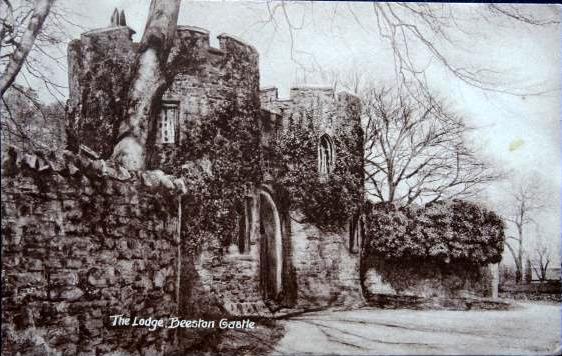
Contemporary postcard showing Beeston Lodge, the entrance to Beeston Castle

The line flourished, even through the depression, and thanks to the patronage of Lord Tollemache, resident in Peckforton Castle, it acquired several more locomotives and stock as other narrow gauge railways sadly closed down.

The line was forced to close during the Second World War and rapidly fell into decline, particularly as its once loyal passengers and local tradesmen turned to road transport.

The last train ran in December 1945 and the track was lifted shortly afterwards.
Nature reclaiming the track after closure
 The locomotives were scrapped though some of the rolling stock has survived to become sheds, hen houses and outbuildings on local farms and small holdings.
Source: https://www.flickr.com/photos/61090099@N04/26102523402
 Some of the trackbed is still extant, though most has now been subsumed into farmland. The wooden station buildings very quickly deteriorated and none now survive, though the concrete foundations of Beeston Castle Station form part of the visitor car park for Beeston Castle.

It was once rumoured that a preservation society might be formed to try and re-open a small part of the line but this has not been confirmed/

For more information see - A Short History of the Peckforton Light Railway


Wednesday, January 01, 2020

How I constructed a rake of Snailbeach-like hopper wagons

As you will be aware from various posts on my blog (eg Freight operations on the PLR and About the Railway), I am interested in running trains for a purpose. My railway serves various lineside industries who (fortunately) make use of the railway to transport raw materials and/or finished products. To increase running potential I recently installed three new sidings on the railway, one of which I designated would be used by a sand quarry. (see Progress Report 75). In reality, there used to be an extensive sand quarry adjacent to the mainline station at Beeston but siting it there on the PLR would have provided very little opportunity for sand traffic on the line, so I decided to shift its location to Bickerton, the other end of the railway which of course, would necessitate the provision of additional traffic. For a while, I considered using the rake of tippler wagons which I already use to transport the ore and spoil to and from the copper mine, however, I felt this would have over complicated traffic movements and so I decided to construct an entirely new rake of hopper wagons specifically for the new sand traffic.
Source: http://www.shropshiremines.org.uk/snailbeach/snailbeach/projects.html
I have always admired the rather quirky wooden hoppers used on the Snailbeach and District Railway system and when I discovered there was a good line drawing in the back of my copy of The Snailbeach and District Railways (Eric S. Tonks, Industrial Railway Society, 2007), I started looking around for a set of donor wagons to short-cut the construction process. I didn't have to look far, in my boxes of bits were a dozen secondhand Hartland Loco Works (HLW) mini wagon chassis which my mate in Australia had sent over when they were thinning out a fellow modeller's collection

A comparison of the dimensions of the HLW chassis with the Snailbeach wagon drawing suggested only a few compromises needed to to be made, though I would have to hack the deck of the chassis about a bit to replicate the open frame nature of the Snailbeach wagons.

After a bit of trial and improvement with a razor saw, I ended up with a chassis which was close enough to the Snailbeach wagon for my purposes and so I then mocked up a couple of hoppers from thin card to produce something which was proportionally close to the original but would fit the aperture in the now hacked chassis. I now felt that construction of the nine wagons needed for the rake could begin in earnest!

Construction process

Modifying the HLW wagon chassis

As the HLW chassis which I had inherited had all been used previously on a fellow modeller's layout, they were a varied mix of parts in a range of conditions.

The first job was to dismantle the chassis into its component parts. They clip together and so just needed to be prised apart.

Next, the upper deck was marked-out to indicate where the cuts would be made. The cut along each side coincided with the mounting holes, 18mm from the edge.

The cuts along the leading and trailing ends were 12mm from the edge, with a 10mm x 10mm protrusion into the hole to accommodate the coupling mounting peg.

After scoring the cut lines with a scriber, a razor saw was used to initially deepen the score lines and then, once the blade had broken through, to finish the cut.

The mounting holes were filled with Squadron White Putty ......

....and sanded smooth.

For chassis which included planking, the divisions between the planks were filled with Squadron White Putty and, once dried, sanded smooth.

The solebars were deepened with the addition of a 5mm wide strip of 1mm thick plasticard. This was glued with VitalBond thick Superglue.

The ends, sides and upper surfaces were scribed by dragging the blade of a razor saw over their surfaces to simulate wood grain.

 Dumb buffers (15mm x 10mm) were fashioned from two pieces of 5mm thick PVC foamboard ....

 .... and attached to the endplates on the headstocks.

  Corner brackets were made with 6mm x 10mm and 6mm x 9mm pieces of 1mm thick plasticard.....

.... attached to the corners with thick superglue.

1mm half round nail art gems were superglued on to the side .......

.... and end brackets to represent bolt heads.

Two 6mm x 86mm lengths of 5mm thick foamboard were glued across the upper deck of the chassis, 38mm from the ends, having been scored with a razor saw for wood grain effect.

Two 132mm x 6mm pieces of 3mm thick foamboard, with 3mm x 18mm notches cut into each end .....

...... were scored to simulate wood grain and then glued beneath the chassis, 5mm in from the sides of the hole.

Two 4mm x 5mm pieces of 1mm plasticard were glued 8mm from the holes and adjacent to the transverse beams on each side of the chassis deck to represent the base of angle brackets to hold the hoppers in place (see below).
Similarly, two 4mm x 5mm plasticard brackets were glued to each end, 27mm from the sides and 5mm from the ends. Two 1mm half round nail art gems were glued to each bracket as bolt heads.


The hopper

The components for the hopper were cut from 2mm thick plasticard to the dimensions shown here:

Planks were then scribed on to each exterior side, at alternating 8mm and 10mm intervals, and wood grain scribed on to the sides with the blade of a razor saw.

The edges which would butt together at an angle were chamfered slightly by dragging the blade of a craft knife along them at an angle. I found the angle wasn't critical as the thick solvent adhesive filled any cracks during construction.

I then glued the four upper parts of the hopper together, using the grid lines on a cutting mat to ensure they were square. Note: The ends were glued inside the sides.

The structure was then flipped over and rested on a couple of offcuts of 5mm foamboard, and two of the trapezoidal lower pieces of the hopper glued on. I found this to be the most successful way of fixing these tricky parts together.

The remaining two lower sections could then be glued on.

Two 32mm x 20mm and two 25mm x 20mm pieces of 2mm plasticard were cut out and scribed across the centre of the 20mm sides .......

.... to form the base of the hoppers. A 25mm x 28mm piece of 2mm plasticard then formed the cap before being glued into the bottom of the hopper.

 Four 25mm x 10mm and four 25mm x 9mm lengths of 1mm thick plasticard were cut and glued to the corner edges of the uppermost part of the hopper to represent metal angle brackets.

Similarly, four 71.5mm x 9mm pieces with 5mm triangles removed from each end were glued along the sloping ends of the hoppers and .......

.......  four 76mm x 10mm pieces of 1mm plasticard, with 11mm triangles removed from each end were glued to the sloping sides of the hopper.

 Finally, four pieces of 18mm x 9mm and four pieces of 18mm x 10mm pieces of 1mm plasticard were glued along the corners of the lowermost section of the hopper.

The straps which supposedly hold the hopper to the chassis were made from 4mm wide strips of 1mm plasticard. The side straps were 45mm in length and 38mm from the ends, and the end-straps 39mm in length and positioned 30mm from the sides. I found it easier to glue the straps to the vertical sides first of all ........

 ...... and then fold them over to the sloping sides.

I used thick superglue with an accelerator spray to fix the straps to the sloping sections to avoid having to hold the straps in position while the plasticard solvent adhesive hardened. The tension in the straps tended to spring them back off again even after I had assumed the solvent had adhered them. With the accelerator spray, the superglue held them firmly after little more than twenty seconds.

1mm half-round nail-art gems were then glued to the brackets to represent bolt heads. Their positions coincided with the centres of the planks but doubled in number at the ends of each bracket. I found the most effective way to fix them was to use a cocktail stick to apply a small dot of thick superglue to the required position .....

.... then use the residue on the point of the stick to pick up a nail art gem.......

....... and transfer the gem to the dot of glue. Because the glue dot was larger in surface area than the tip of the cocktail stick, the gem would happily become detached and glue itself to the model. It could be repositioned with the point of the stick to ensure it was in exactly the right place.

Any excess glue could be removed with a small piece of paper towel.

I decided not to add gems to the lowermost section. partly because it would not be seen and partly because it was a tight fit into the chassis and I didn't want anything interfering with the fit.

The chassis and body were now ready for painting. A couple of coats of Halford's grey primer from a rattle can and then the metal fittings were picked out with black acrylic paint using a fine paintbrush.

Final Assembly

I toyed with several ideas for joining the hopper to the chassis - even experimenting with brass strips and escutcheon pins on an early prototype, but I was not happy with the results.

So, eventually, I decided to keep things simple. I happened to notice that the black cable ties which I had in store were 4mm wide and also that if I carefully removed the ratchet catch from the end, they could quite convincingly represent the ties holding the hoppers to the chassis. Slots were cut into the hoppers at the ends of the retaining straps and also in the chassis at the ends of the bracket-based. The cable ties were then threaded through these slots........

..... and held loosely in position with the ratchet catches which had been removed from the ends.

Once all eight cable ties had been threaded through, they were tightened in sequence (opposites first) .......


...... until the hopper was held tightly and evenly on to the chassis. The excess lengths of cable tie were snipped off.

Brake gear was manufactured from pieces of brass strip. The vee-hanger, 20mm x 8mm, the outer hangers 24mm x 4mm (with 4mm at the end folded up), the catch bracket 50mm x 4mm, with 20mm folded up behind and 1mm holes drilled at 3mm intervals. The brake lever 45mm long, 4mm wide, tapering to 2mm. The actuating arms 28mm long and 3mm wide and the shoes 10mm x 5mm filed to a concave profile as shown.

These pieces were soldered together with domed escutcheon pins inserted into the pivots, using a simple jig to hold everything in place for soldering.

An 85mm x 126mm piece of 4mm ply was cut out, as was a slightly larger piece of foam packing (I would have used expanded polystyrene but had none available).

The foam was stapled to the ply, leaving one edge unstapled so scraps of foam could be inserted before the final edge was stapled.

Strips of ply or balsa wood (whatever was to hand) were then glued beneath for supports, ......

.... before the foam was smothered in PVA and fine sand sprinkled over.

The load was then inserted into the wagon. Some trimming was necessary on some of the wagons to ensure that the loads could easily be removed to allow the wagons to run Down the line as empties.

The wagons were then lightly weathered. Firstly being daubed with a thin black/brown mix of acrylics, which was wiped off while still wet to leave deposits in the cracks and crevices. Orange, brown and burnt sienna acrylics were then stippled on to some areas of metalwork to simulate rust and rust streaks.

The whole process was repeated another eight times, with some batch-production taking place to ease the construction process.

You might notice that some of the wagon chassis have not retained the coupling mounting bracket. I decided that I would make two rakes of four wagons and permanently couple them together with chains - thus obviating the need for coupling mounts except at the end of each rake. The ninth wagon has couplings at both ends allowing it to be added or removed from the rake should, for example, I decide to include a different wagon in the two rakes of four to transport other supplies to the quarry.

 The wagons are mounted on Bachmann 24.5mm metal wheels which are smaller than the 32mm plastic wheels provided with the HLW wagons. This brings the deck of the wagons down more closely to prototypical level above the rails. By coincidence, these were the wheelsets which I inherited with the wagons - a happy coincidence!

I have developed my own form of LGB style hook and loop coupling which is less obtrusive than the plastic originals but which retains the advantages of hook and loops - ie cost effectiveness, reliability and ease of coupling/uncoupling. More on this to follow (see How I constructed replacements for LGB hook and loop couplings)


Conclusion

I am pleased with the outcome. The wagons retain some of the charm of the Snailbeach originals but, because they have been constructed on tried and tested HLW chassis they are almost totally reliable. I have had to make a few compromises in their design, but my railway doesn't profess to be a scale model of any particular prototype. As I always say, my models are 'inspired' by the originals.

The wagons have entered service and nicely augment traffic on the line. This now means I must have at least four locomotives in steam during an operating session and integrating the quarry trains into an already packed working timetable adds yet another complication. Certainly one which I relish!

The quarry siding has been enhanced with some loading hoppers for the wagons (see How I constructed some loading hoppers for the sand quarry - pending). I am now trying to figure out whether I ought to try modelling the interchange sidings at Beeston Market where the sand and copper ore trains unload on to either canal barges or mainline wagons. An interesting proposition!

A short video showing the wagons in action - before they were all weathered.