Monday, September 07, 2020

How I constructed a luggage van by 3D printing

Until now, my 3D printing projects have focused on downloading and printing-out various items created by other people (eg seeHow I constructed a 3D printed beam engine and  How I constructed a 3D printed diesel loco - pending) or drawing simple objects for printing such as the seats for my CVR railcar or the window frames and ridge tiles for the Boneworks building.

After struggling unsuccessfully to produce viable 3D drawings with Sketchup, I came across TinkerCAD which seems better suited to the way I think and learn - see How to draw a window frames with TinkerCAD. Having mastered fairly simple drawings, I decided to try using TinkerCAD for something a bit more challenging - a complete wagon.

 The first task was to research the type of wagon I wanted to produce. Having recently finished constructing a model of the CVR railcar, I felt it needed a small luggage van to tow. I tracked down a couple of photos of a County Donegal luggage van .......

..... and sketched out some rough dimensions for it, using the Hartland Loco Works (HLW) mini-series wagon chassis as the starting-point.

A large proportion of the wagons on my railway have made use of HLW chassis. They were once cheap (around £10GBP) and plentiful. Unfortunately, HLW have recently ceased trading and so, apart from residual stocks in a few shops and secondhand models the supplies will dry up completely - unless someone produces a 3D printable alternative (see below).

Once I had a rough sketch, I started by creating the side of the van in TinkerCAD.


The side is simply a series of rectangular blocks of various sizes linked together. The tools in TinkerCAD are cleverly designed to make repetitive tasks easier and so planks, for example, can be repeatedly copied, pasted and moved a set distance through the use of the 'Duplicate' tool. (See How I drew a window frame with TinkerCAD )

Once I was happy with the side, I then drew the end.


The trickiest part was drawing the curved section. After a couple of abortive attempts, I remembered that I had used a large dinner plate as a template when creating similar curves on models and so drew a large disk and sliced it off to produce the arc for the roofline.

These two parts were then exported as .STL drawings, imported into my slicing software (Cura) and printed each out twice.

The sides are designed to slot into the recesses in the ends and so, after a little bit of tidying with a file, the van was put together as a dry run. Comparing it with the photo, I realised I needed to make some adjustments to the parts and add some detailing.

The detailing on the sides was added first. Various strips of 1mm thick plasticard were cut, shaped and applied to represent the strapping and hinges. A length of 1mm brass rod was fixed in place to act as the door catch and four pieces of half-round brass were cut and attached to represent the hinges.

The process was repeated for the other side.

The sides were then glued to the ends.


My initial thought was to make the roof from single curved piece of plasticard, but in the end I decided to form it from plasticard planks. To support these, two roof supports were drawn and printed. The drawing for these was simply achieved by slicing off the top of the drawing of the end.

 10mm wide strips of 1.5mm plasticard were then cut and glued to the roof, starting at the outer edges and moving in towards the middle, so the final strip could be cut to fit (it was 4mm wide).

A piece of 0.5mm plasticard was then cut to size and carefully glued over the planks, starting on one side and applying liquid solvent in strips until the whole roof covering had been applied.

The body was then loosely fitted on to a HLW chassis and checked to make sure it looked OK and rand smoothly.

It was then given a couple of coats of Halfords' grey primer ........

.... before 1mm half-round nail art gems were applied to represented rivet and bolt heads.

I use thick superglue applied with the end of a cocktail stick to fix the gems in place. I find that there is usually sufficient residue on the end of the stick after using it to apply the dots of glue to pick up a dot and transfer it to the model.

The strapping, hinges and catches were then picked out in black acrylic paint and the roof given a coat of dark grey acrylic. The padlock (a small piece of plasticard with a 1mm brass rod hook) was painted gold.

As can be seen, the van looks OK behind the railcar. It's maybe a bit on the small side, but that's because I had no dimensions to go on and so based them on the size of the chassis - adjusting the dimensions so it looked in proportion.

There were various types of luggage van used on the County Donegal and some of them were about this size - though of a different design.

As you can see, I have added my own style of LGB hook and loop couplings, Bachmann 24mm metal wheels and Binnie Medium Carmarthen buffers,


POSTSCRIPT

I decided to develop my drawing skills further and add the details on to the 3D drawing in TinkerCAD.

I have now printed these new sides and ends out.

 The detailing seems to have come out well, ......

.... so I am encouraged to keep developing my skills in TinkerCAD.


I also decided to draw and print-out interlocking planks for the roof;

 ..... so it would make a more or less complete model.

At the same time, as HLW chassis are now no longer in production, I drew and printed out my own version - using the same dimensions .....

.... but with my own design of solebars, as I was never entirely happy with the look of the HLW solebar. I think my version looks more UK-based. It should be, I used photos and drawings of the Southwold Railway wagons as my guide!

The chassis glues together quite simply .....

... and can be used with Bachmann 32mm or 24mm wheels as with the original HLW chassis.


I have made the .STL files for the van and the chassis available on Thingiverse should anyone want to have a go at printing them out for themselves.


Post-Postscript

 I have now modified the chassis sides to include a simplistic representation of brake gear.

For me, TinkerCAD uses a far more logical approach to the production of 3D drawings. Drawings are produced by manipulating and joining three dimensional objects on the screen, whereas in programs such as in Sketchup, shapes are produced initially in two dimensions and then extruded into the third dimension. I suppose they are designed primarily for those who are used to using 2D CAD packages. 

I shall carry on tinkering with TinkerCAD. I find the logistics and skills needed to produce a decent 3D drawing every bit as rewarding and stimulating as making a model from scratch. And there is something very satisfying in watching the printer churning out something I have drawn.


Monday, August 31, 2020

Progress Report 83

 The weather this August in the North West of England has been mostly wet, cold and windy - not the best conditions for running trains in the garden. However, it has provided plenty of opportunity for work to be carried out on projects in the workshop.

Lineside

Boneworks

Work has been progressing steadily on the boneworks which will be situated on the new siding at Bulkeley station. The model is based on the Bone and Flint Mill at Etruria in Stoke on Trent.

The concrete base on which will sit has been cast ......

..... and the walls have been scribed with brickwork.

The roof has been tiled .......


..... and the window frames and ridge tiles have been drawn in TinkerCAD (see How I drew window frames for 3D printing with TinkerCAD) .......

....... and printed out.

The next stage will be painting and final assembly. Hopefully, not far to go now.

Beam engine

In the meantime, I downloaded and printed out the parts needed to make a beam engine from the Thingiverse website.

There were 54 different parts, some of which needed to be printed more than once ( eg two halves of the flywheel, the beam, the bearings, etc.) and so I worked out my printer was in action for 47 hours 1min. However, I am very pleased with the outcome.

The beam engine will be situated inside the engine house of the boneworks, which has a very large window and so will be highly visible.

For more information, see How I assembled a 3D printed beam engine

Rolling stock

With over 70 items of good rolling stock, six coaches and 18 locos, the Peckforton Light Railway has probably reached maximum capacity, however I find it difficult to resist the temptation to add another item of stock when something takes my fancy.

Car railcar

When tidying my shelves I came across a dismembered car railcar which I had picked up on eBay a couple or more years ago. As bought, it was mounted very high above the track with an over-sized bogie supporting the front end. I had shelved it with the intention of finding a way of modifying it to sit lower on the track.

Once I started tinkering with it, I couldn't stop and after a couple of days the transportation for Lord Tollemache's eldest daughter was born.

For more information see How I made a car railcar.

Luggage van

Having got to grips with creating my own 3D drawings with TinkerCAD, I decided to try drawing something a bit more ambitious.


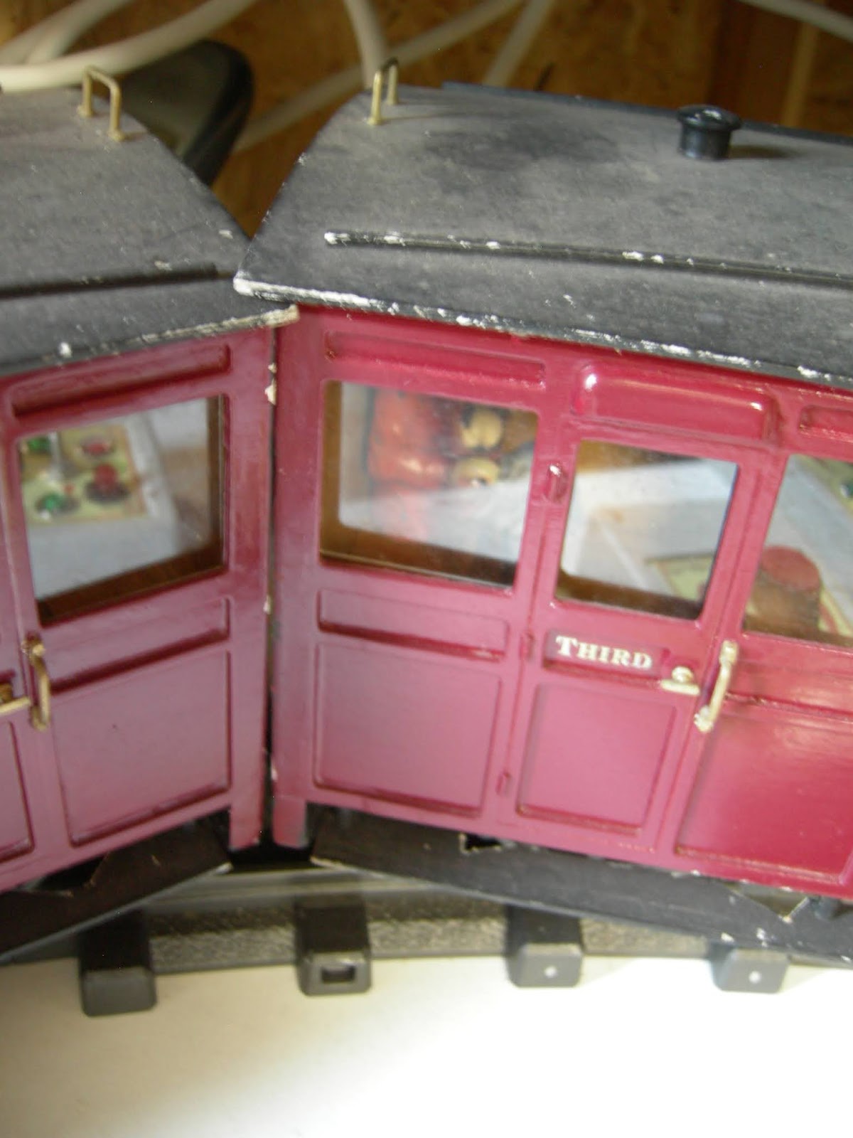
I drew a side and an end for a luggage van to tow behind my recently finished County Donegal railcar - See How I constructed a CDR railcar - pending

The sides were printed out and some additional details added with plasticard and offcuts of brass section

Couplings for Maddison coaches

For the past two years I have been steadily replacing LGB plastic couplings on all my rolling stock with my own slimline wire and brass rod versions. The last three items of rolling stock to be converted were the Maddison coaches. In addition to adding couplings, I needed to mount buffers on swivelling arms attached to the bogies. At the same time, I increased the distance between the coaches to enable them to negotiate the tightest curves on my railway as previously the coach roofs touched.

The couplings have now been installed .......

..... and at the same time I tidied up the paintwork and added PLR emblems.


Other

3D printer

 As indicated above, I have been pressing my 3D printer into service on a range of projects. I have also been steadily adding enhancements such as a Y-belt tensioner, a cooling duct for the printhead and a glass print-bed.
[Awaiting photo]


Z axis problem

A problem which surfaced when printing out parts for the beam engine is that there seems to be a bug in the firmware for the Z-axis. It's not insurmountable but somewhat irritating. The printhead seems unable to print anything taller than 36mm. I have tried several approaches to sort out the problem following suggestions on various 3D forums, all to no avail. Eventually, I may have to update the firmware but this might be difficult as I cannot get the printer to communicate directly with my laptop. In the meantime, I have been chopping taller parts into sections shorter than 36mm, printing out the sections and then gluing them back together again, such as the pillar for the beam engine.

I see this as an inconvenience rather than a major problem - after all, the printer only cost me £80, so I must expect some teething problems.

Sunday, August 30, 2020

A 3D printed beam engine

 Having recently acquired a (very) cheap 3D printer new for £80GBP (see How I assembled my 3D printer), I have pressed it into service producing a range of items both downloaded and original (eg see How I drew window frames for 3D printing with TinkerCAD). My present project is a boneworks for Bulkeley Station (see How I changed the layout at Bulkeley and How I constructed the boneworks). My model is based on the Etruria Bone and Flint Mill in Stoke on Trent which boasts an engine house with Watt beam engine to power the grinding machinery. The windows of the engine house are quite large and so the beam engine will be visible inside it. I therefore needed to find an appropriate model beam engine to sit inside. A quick search of the Thingiverse website revealed a suitable candidate - https://www.thingiverse.com/thing:1350988.

The 54 parts needed to make the model were duly downloaded and printed out - which took nearly 48 hours of printing time.

Fortunately, the download includes a comprehensive set of assembly instructions and so I was able to follow them. However, I ignored the recommendation to use epoxy and defaulted to my usual Vitalbond thick superglue.

The first task was to glue together the two halves of the flywheel. It was at this point I recognised the wisdom of using epoxy as it provides far more wiggle-time to ensure the two halves are perfectly aligned. The two halves of my flywheel are a few millimetres out of alignment and I was unable to correct this as the glue had set.

The next task was to glue the two base sections together. As the firmware on my printer has a bug which prevents me from printing anything taller tan 36mm, I had to slice the two sections in half vertically (using TinkerCAD) and then rejoin them before gluing the two base sections together.

The upper surfaces of the base sections were then glued in place.

The two halves of the crankshaft were then joined with the crankpin, onto which had been threaded the main crankshaft. A jig was provided in the kit to ensure the two halves of the crankshaft are properly aligned.

The bearings for the crankshaft were then screwed to the baseplate with 2mm screws.

The valve actuator arm was then threaded into the upper half of the valve chest........

..... and held in place with a butterfly shaped retainer which was fixed with a small dab of glue applied with a cocktail stick.


The two halves of the valve chest were then united.

The beam bearings, bearing plate, pillar and base ring were then located ......

..... and joined together with glue and screws.

Two short linkages and two long linkages were then interlinked with the piston rod using one of the bolts. A nut was glued to the end of the bolt with a small dab of glue.

The other two short linkages were then threaded on to the linkage pivot pin which in turn was threaded through the ends of the long linkages.

A small dab of glue held the two linkage pivot arms in place.

The two halves of the beam were then identified, together with the large bolt and nut which holds them in place.

The linkage assembly was attached to one end of the beam with another bolt and nut.

Another bolt and nut was used to connect the other end of the linkage assembly to the beam.

The beam with its linkages ........

.... was then joined to the pillar with the large bolt and nut for the main pivot and two short bolts and nuts for the linkage assembly.

The cylinder top plate was then glued to the cylinder and the piston and inside of the cylinder filed smooth to allow the piston to slide up and down inside.

The piston was then glued to the end of the piston rod.

The two halves of the cam were then threaded on to the end of the crankshaft, sandwiching the valve connecting rod between them. Small dabs of glue held the cam sections in place and then a pulley and end-cap were attached to the end of the crankshaft. The flywheel was similarly attached to the other end of the crankshaft.

The other end of the valve connecting rod was linked through the valve actuator and fixed in place with a small nut. The pressure gauge and control levers were glued to the valve chest.

The flywheel was then given a few spins to make sure everything was functioning as it should.

The steam pipes and flanges were then glued to the valve chest and brackets, ......

..... and the cladding for the cylinder slipped into place. These are removable, partly to help with painting and partly to allow the piston to be viewed inside the cylinder.

The main structure for the beam engine was now complete.

Although the quality of printing which is achieved by my printer is not the best - particularly in the vertical (z-axis) plane, I had decided not to spend a lot of time smoothing down the parts as the beam engine would only be visible through the engine house windows and hence not attract too much scrutiny.

I was pleased to find that it was very smooth in operation and quite robust. I accidentally knocked it off the workbench and on to the floor on a couple of occasions and it survived this maltreatment well.

Now I was satisfied with its construction, I turned my attention to motorisation. A small 3v motor was clipped into the motor clip and a AAA battery holder and switch wired up. The motor arm has been carefully designed to allow these to fit snugly in place.

 The pivot for the motor arm was then glued inside the base section and a piece of shrinkwrap tubing threaded on to the motor shaft and shrunk on to make a tight fit. The motor shaft bears directly on to the outside of the flywheel, and allowed to pivot to compensate for any undulations in the flywheel circumference.


However, even when using a 1.2v rechargeable cell, you can see the speed at which the beam engine operates is far too fast, so I experimented with a couple of alternative solutions.

Eventually, I designed, drew and printed out a sleeve which allowed me to put a small 12v geared motor into the motor bracket. I added a few pieces of lead flashing to act as a counterbalance. I found that a plastic wheel from a cheap plastic model car provided about the right speed when bearing on the outside of the flywheel and so this was forced on to the end of the motor shaft.

The pivot for the motor arm needed to be shifted and another hole drilled beside the flywheel.

A PWM motor controller was acquired (£3.65GBP from eBay) and wired up to three AAA 1.5v cells to allow me to fine tune the speed.

The model was then painted with acrylic paints. As you can see, I opted for green for the main components .....

.... and red for the minor components.

The bearings and piston rod were picked out in silver

.... and the bands and bolts for the cylinder picked out in gold. The cladding was made to look like varnished wood and the stonework for the plinth was painted brick colour with grey/cream mortar courses.

I am now very pleased with the way it has turned-out. As you can see, I can vary the speed at which operates and may eventually link it to a 12v supply which I intend to install for station and building lighting at the station. The PWM controller can cope with up to a 16v supply.

I congratulate the designer of the beam engine who I think has done a marvellous job and then shared his hard work with the rest of us for free. All I need to do now is finish off the building in which it will be housed!