 I have never felt particularly confident about making my own powered chassis. It's partly because I don't really have the workshop equipment needed for accurate metal working, but also because I don't really have the skills and aptitude necessary for the sort of precision engineering which the creation of reliable working mechanisms require. However, with the advent and my acquisition of a 3D printer that has now changed.
It all started when I constructed a Glyn Valley Beyer Peacock locomotive and powered it with a secondhand Bachmann motor block from a tramcar.

I was very disappointed with the loco's hauling capabilities. Clearly, a mechanism designed for a tramcar wasn't expected to pull heavy loads!
The beauty of the Glyn Valley locos is that they were designed to run along the roadside, and so their motions were covered with side-skirts (so horses wouldn't be frightened). Thus, any sort of mechanism can be used to power a model, as it wouldn't be visible.

And so, I decided to have a go at using my TinkerCAD designing skills and my 3D printing capabilities to create my own powered chassis. After all, filament 3D printers can work down to 0.2mm of accuracy.
My first design made use of the ubiquitous 12v MFA Como 918D gearbox motor. These have been used extensively in garden railway locomotives for years.
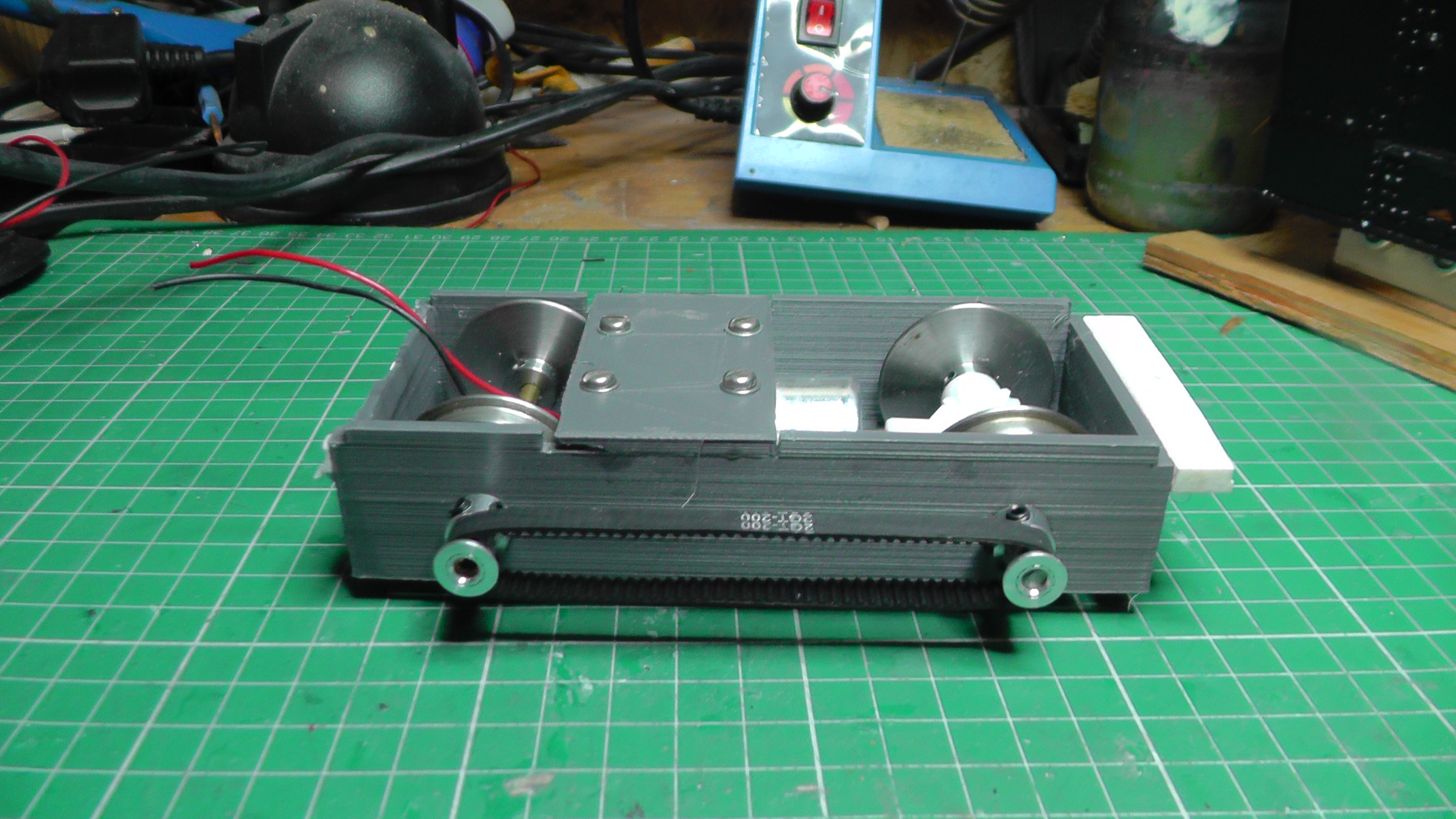
The motor quite happily sat between the axles, driving one of them via bevel gears (also obtainable from MFA Como). The power was then transmitted to the second axle via a toothed belt and toothed pulleys ....

... acquired through eBay.


The wheels were provided by Essel Engineering with 4mm diameter holes for axles (the bore of the bevel gears). The beauty of 3D CAD and printing is that I could easily tweak the design to, for example, ensure the bevel gears meshed perfectly.
This fitted snugly inside the skirts of the GVT loco and she was given a test run.
However, I was disappointed to find that it was only marginally more powerful. The eight wagon goods train in this above video barely made it up the 1:40 gradient on full power. I needed to find a more powerful gearbox motor.
I opted for a MFA Como 940DLN 51:1 gearbox motor which was considerably larger than the 918D and so the chassis needed to be redesigned to accommodate it.

The toothed belt was replaced with connecting rods and fly cranks attached to the ends of the extended axles with grub screws inserted into square nuts trapped in the fly cranks.


The loco now performed a lot more powerfully - actually she is now far more powerful than she needs to be - the 51:1 gear ratio is probably lower geared than is necessary which means her top speed is somewhat reduced.
I rested on my laurels for a year or so until I encountered another chassis problem. A 3D printed Ruston diesel loco body which I had designed to fit on to a HGLW Deluxe powered chassis. Whilst I was pleased with the loco body, it just didn't look right perched on top of the HGLW chassis. Nothing wrong with the chassis - they are sturdily designed and easy to construct - it just wasn't appropriate (see How I created a sort of Ruston diesel).

So, another bespoke chassis was required. This time, rather than going down the MFA Como route, I decided to explore Polulo geared motors which, according to their data sheets, provide higher torque than their MFA equivalents - though they are more expensive.

The wheels are Bachmann 24.5mm metal wheelsets on 3mm axles.
For its size, the chassis is quite powerful. I've not yet been able to test it to its limit, as the wheels slip before it stalls, but I suspect it will have more pulling power than the first GVT loco chassis I constructed.
I ended up abandoning the Polulo gear motors in favour of much cheaper GA25-370 gear motors from AliExpress. These have proved to be just as powerful and reliable.

The bevel gears also came from AliExpress......

..... as did the top-hat bearings.

The Delrin chain and sprockets were provided by MotionCo.

This chassis enabled me to more realistically mount the body far closer to the rails.

Since this build, I have used an identical chassis to power a Ruston Proctor oil engine (see How I constructed a Ruston Proctor loco), ...

......and, with some modification to allow the motor to fit inside the vertical boiler, ......

...... a de Winton locomotive. This did not require chain drive as it has coupling rods mounted to inserts on the wheels (for more information see - How I created a de Winton vertical boilered loco.

So, how did I go about the design process for the powered chassis?
How I designed the chassis
As has been mentioned, my 3D CAD package of choice is TinkerCAD. It is not the most powerful or sophisticated package, but I find it easy to use and more than capable of the design tasks I have used it for over the years.
I have provided some tutorials on making use of TinkerCAD plus there are dozens (if not hundreds) of video tutorials on YouTube.
What I found essential was to recreate a 3D version of the motor and the bearings.

I could then 'build' the chassis on screen.

As can be seen, the chassis is little more than a series of simple building-block shapes.

With TinkerCAD, any shape can be turned into a 'hole', such as the motor assembly.

When a 'hole' such as this is combined or 'grouped' with another shape, such as this red block......

... the 'hole' creates a concave image of itself in the other shape

In the same way, 'holey' copies of the axles and the bearings can create the correct sized and shaped holes in the main chassis block.


And so, the various components can be grouped together to create a bespoke chassis block. In this version, the base is removable to allow Delrin sprockets and chain to be more easily fitted. It also has three sets of axle holes to easily allow for different wheelbases.

This chassis is available as a free download on the Gardenrails.org forum. You will need to register to download the file, but access is free (though voluntary donations for the running of the forum are always gratefully received).
Construction of the chassis
Once the two parts of the chassis had been printed out.......

..... the bearing bushes were inserted into the four axle holes. I have tried using superglue to hold them in place but, as they are made from oilite bronze, they aren't susceptible to gluing.

As mentioned above, I used Bachmann 24.5mm dia wheelsets. The wheels can easily be removed from the axles with a bit of gentle force and a twisting action.


With one wheel removed from each wheelset, the axles were then inserted with a washer between the wheel and the chassis. The Delrin sprocket was also placed on the axle with a spacer washer ........

..... before the second wheel was put back on to the axle.

This process was repeated for the other axle, but with a 3mm bore bevel gear also inserted.

Before the second wheel was attached, the Delrin chain was fitted, the slack provided by the end of the axle being handy for tensioning.

The second wheel was then placed on the axle.

A 4mm bore bevel gear was attached to the motor shaft and the motor slipped into its housing. Some adjustment was required to the positioning of the bevel gears to ensure they meshed smoothly (a cigarette paper's gap should be left between the teeth).

The base was then attached .......

.... and held in place with cable ties inserted either side of the motor and tightened to hold the motor in place.

I left the extended axles on at this stage, as I wasn't sure whether the chassis would be used in a loco with fly cranks. If not, the ends of the axles will be easily removed with a slitting disk in my mini-drill.

I have been pleasantly surprised at how quiet and powerful the chassis are - as evidenced in these videos.
The only limitation to the load the de Winton (and the other locos) could pull was adhesion - the amount of weight I could squeeze in was limited by the available space.
Armed with the above experience and accumulated confidence, I am now happy to experiment with other powered chassis. I just need to track down some decent spoked loco wheels (or print my own!).
