Monday, February 22, 2021

How I converted a Bachmann Lyn into a Schull & Skibbereen 0-4-4T

Having acquired a Bachmann Lynton & Barnstaple Lyn loco for a reasonable price and converted her to battery RC (see How I converted  Bachmann Lyn to battery RC), I was concerned that there were a few problems with the way she ran on my railway. Firstly, the overhang at each end was so great that the out-swing on my tight curves caused problems with the couplings. Secondly, the scale was wrong. The Bachmann loco is constructed to a somewhat unusual scale of 13.8mm to the foot, which makes her slightly under-scale for my 15mm / ft railway. Presumably, this is a compromise between the 1' 11.5" gauge of the L&B track and the 45mm gauge of the model.

So, should I live with the anomalies, modify the body or find a more appropriate model which could be mounted on the motor block? In the end, I decided on a compromise. I found a very attractive 3' narrow gauge  4-4-0T loco which ran on the Schull & Skibbereen Railway in Ireland. 

Source: https://durrushistory.files.wordpress.com/2014/08/07-img_4667.jpg

However, the S&S loco had inside frames whereas the Lyn has outside frames with fly cranks. I then discovered a Cork & Muskerry 0-4-4T loco with outside frames but I didn't like the body as much as the S&S loco, so I decided to merge one with the other. 

The 7mm narrow gauge modellers' association have produced a beautifully detailed scale drawing of the S&S loco but, as far as I know, there is no drawing of the C&M loco. I therefore had to study the few photos which exist of the C&M loco to marry the Bachmann chassis with to the actual 0-4-4T chassis. Quite a few compromises were made as the wheelbase and driver diameters are not equivalent, but I have never let such details previously interfere with my model making. Undaunted, I pressed on by superimposing the motor block dimensions on the drawing.


The body needed to be lowered, the front of the running plate needed to be shortened and the rear bogie needed to be compressed slightly, but I felt it was feasible.

Unlike my previous scratchbuilds, I decided to construct this loco entirely from 3D printed parts which I firstly needed to draw with a 3D drawing package. I opted for TinkerCAD, an online 3D drawing app which is designed for kids to use so it has a very gentle learning curve. However, despite its fairly limited tools, it is capable of producing quite detailed objects.


As the build was going to be quite ambitious, compared with my previous efforts (eg see How I drew a Southwold Railway open wagon with TinkerCAD), I decided to combine each of the parts into an overall drawing of the loco, partly to check they would fit together and partly so I could see what the loco looked like.


After drawing all the principal parts of the loco and printing them out, ......

...... I started on the construction. 

The rear of the cab was glued to the footplate .......


...... followed by the cab and tank sides.

The front of the cab with the rear of the boiler was then attached.

The smokebox was attached to the front of the boiler, .....

..... and the two halves of the boiler were united.

The tops of the tanks were then glued into place, together with the fronts of the tanks

At this point, I realised that I needed to fit backs to the tanks so these were cut from 2mm thick plasticard. The backs of the tanks were later reproduced as TinkerCAD drawings.

I then tackled the four wheel trailing bogie. I decided to use the two two-wheel bogies from the Bachmann Lyn as these included neatly engineered sprung suspension. The two bogies were shortened.....

.... and extraneous mouldings removed.


They were then joined with a short piece of aluminium plate with self-tapping screws,.......


...... and the outside frames glued into place  .....

....using a bracket printed in TinkerCAD.


A bracket for my own style of hook and loop couplings was then screwed on the the base of the bogie.... 


..... and everything given a couple of coats of Halfords grey primer from an aerosol rattle can, followed by a brush-painted coat of back acrylic.


The dome, chimney and safety valve were then glued on to the top of the boiler  and the toolboxes(?) were then glued either side. The motor block was test-fitted as was the bogie to make sure I had got the dimensions correct.


I realised that there now needed to be some infill beneath the running plate and so, after mocking something up from oddments of plasticard, I then reproduced the two sub-chassis pieces in TinkerCAD. One for the front ......


.... and one for the rear.

The rear part was glued beneath the footplate ......

 A self-tapping screw holds the rear of the motor block to the bracket ......

.... and the bogie was connected to the rear of the motor block using one of the original pivot screws and pivot hole.

 The front part was left floating so that it could be screwed into place with a single screw to serve a triple purpose: infilling beneath the running plate, retaining the cylinders and also acting as a bracket to hold the front end of the motor block. A mounting block for my hook and loop couplings was then glued on.


At this point, I realised that the body was sitting slightly too high on the motor block and so, by whittling away at the running plate, the toolboxes and the boiler, I was able to to lower it by around 5mm. I now felt the loco was looking more realistic.


The firebox was glued into the cab and I glued the steps to the footplate. However, these later needed to be removed as the bogie swings out too much when taking my tight curves.

The loco then went into the paintshop and given a couple of coats of Halfords grey primer from a rattle can aerosol. This was allowed to harden off overnight before the various cracks and cavities were filled with Squadron White Putty. The body was then rubbed down with 80 grit followed by 240 grit emery papers. Another coat of primer was then followed by four light coats of Halfords Rover Brooklands Green body spray.

Handrail knobs from Garden Railway Specialists were then glued into holes drilled in the boiler and smokebox and brass rod passed through and shaped into handrails.


 The interior of the cab was painted with cream coloured acrylics and the pipes, regulator and knobs on the backhead were painted copper, gold and red.


Electrics

My standard battery/RC circuit was used for this loco - three solder-tagged 18650 li-ion cells (from Ecolux) were wired up to a 3S battery protection board and a four-way JST balance charge socket. This was in turn wired through a Single-Pole Double-Throw (SPDT) toggle switch to a DC power socket and to a Deltang Rx65c receiver/controller and a MyLocoSound Universal Steam Soundcard.


She has so far had a couple of test runs and required a small amount of modification to ease the motion, but looks as if she will make an interesting and slightly different addition to the fleet.


[Awaiting video of first run]


Progress Report 88

 In my last progress report, I complained about the weather. It certainly hasn't improved since then; two weeks of freezing temperatures, followed by another weeks of rain. This hasn't been entirely conducive to running trains out in the garden, but it has encouraged me to spend a fair amount of time in the workshop.

Most of this time indoors has been spent drawing, printing and constructing a Schull and Skibbereen locomotive using the Bachmann Lyn motor block from the battery conversion described in my last Progress Report.

In between waiting for glue and paint to set, I spent a few hours cataloguing my YouTube videos of the PLR and shooting a short intro to my railway for a short TV news item on the railway.


Schull & Skibbereen loco

The drawings were produced using TinkerCAD, which is an online 3D drawing tool which is very easy to use and, with some imagination and a bit of dexterity, is capable of producing quite detailed 3D drawings.


The body is based on a three foot gauge 4-4-0T Nasmyth & Wilson locomotive which ran on the Schull and Skibbereen Railway in Ireland.

Source: https://durrushistory.files.wordpress.com/2014/08/07-img_4667.jpg

The chassis was based on another Schull & Skibbereen Railway locomotive (an 0-4-4T) which was more suited to the Bachmann Lyn motor block which has outside frames and fly cranks. Unfortunately, I can't find a copyright free photo of this loco, so you'll have to take my word for it.

After printing out the various parts, .....

 ..... they were assembled and painted to produce which I think is an attractive and slightly different type of locomotive to those already in existence on the PLR.


There's still a bit more detailing to do - more pipework, nameplates, number plates and makers' plates. She is powered by three 18650 li-ion cells and controlled via a Deltang Rx65c receiver/controller. She is also equipped with a MyLocoSound Universal Steam soundcard. For more information, see How I constructed a Schull & Skibbereen (ish) 0-4-4T loco


Southwold Cleminson open wagon

 I have finished constructing the Southwold Railway 6-wheel Cleminson open wagon but am not at all happy with its undercarriage. I decided to try a different design for the centre truck from that I used on the passenger coach, but it has not been as successful as I hoped. Although it overcomes the need to widen the centre truck to cope with tight curves, the truck is less well supported and so flops around dramatically until it is placed on the track. I will need to go back to the drawing board to find some sort of compromise.


Video catalogue analysis

After trawling through dozens of the 103 videos which I have so far produced and uploaded to YouTube featuring the PLR, I decided to catalogue every video showing which locomotives, trains and locations they portrayed, using a Google Sheets spreadsheet.

As well as showing the content for each video, I added a simple analysis of the frequency of occurrences of each loco, train and location, which proved fascinating.

As you can see, Peckforton Station seems to be my favourite location and some locos appear far more frequently than others. I will try to address these imbalances in my future videos.


The PLR on TV

At the end of each week on out local BBC TV News programme, there has been a short item on activities which viewers have been involved with during the most recent Coronavirus lockdown. After alerting the producers to some of my YouTube videos, I was contacted by the presenter who asked if I could shoot a short introduction to camera for inclusion in their next broadcast.

I hope my short item will encourage others to venture out into the garden ......

The hours of daylight are now lengthening and the weather seems to be improving slightly. I am becoming impatient for getting outside to make some improvements to the trackwork at Bulkeley and Beeston Castle stations which challenge my six-wheel Cleminson ex-Southwold Railway coach. Also, I want to give my new ex Southwold goods stock a proper run.

Fingers crossed ......


<<< Previous progress report     -.    Next progress report.  >>>


Sunday, January 31, 2021

Progress Report 87

The Northwest of England seems to have suffered the worst of the country's winter weather since my last update. Cheshire was particularly badly affected by flooding and, although this didn't affect the Peckforton Light Railway directly the canal adjacent to where Beeston Market station would have been located was breached after Storm Christoph blew through the area. This is reminiscent of the Big Wind which affected the area when the railway would have been in existence. In addition, we have had more snowfall than we have had in previous years which was eventually appropriate for a partial running session.

On a personnel front, the Chairman /  Chief Operations Officer has celebrated a significant birthday which resulted in the acquisition of a secondhand Bachmann Lyn which has been on the wishlist for many years. The day after my birthday, it was converted to battery power and radio control.


Rolling Stock

Bachmann Lyn

Having been offered a secondhand Bachmann Lyn for a reasonable price, I was anxious to convert it to battery power and radio control to see it running on the railway. Despite the weather, she was given a test run together with the new Southwold Railway goods stock described in my previous Progress Report.


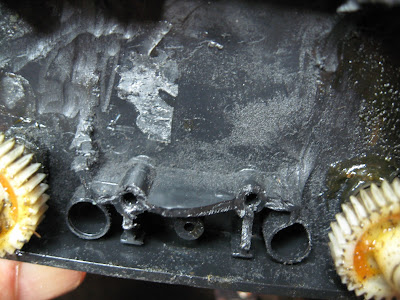
The Lyn is one of the earlier designs and so the motor block is suffering from the adverse effects of the poorer quality brittle plastic from which the clamshell casing is constructed. One of the lugs for the screws holding the body to the block had disintegrated as had one of the lugs for the outside frames and, more significantly, one of the lugs for the screws holding the clamshell together. 

Having now given it a test run on the tight curves on my railway alongside my rolling stock I have realised it is not really appropriate for the PLR in its present form. After searching about for a suitable prototypical loco to convert it into, I have settled on a hybrid of two Cork and Muskerry locos - an 0-4-4 side tank loco with outside frames.


 As you can see, I have decided to model this loco as a 3D print. This is a bit of an experiment, as I have not modelled anything quite so ambitious from scratch. I have found it a bit of a challenge to design the loco so that it can be broken down into parts suitable for printing on my 3D printer. I am reasonably optimistic that it will work - as they say, watch this space!


Southwold Cleminson Open

I am steadily working my way through the variations in designs of Southwold freight stock. The various versions of the three plank open have now been catered for and, in time, I will print out at least one of each variant.

I have now turned my attention to the Cleminson six wheeled open wagons. As with the four wheeled opens, there was a range of styles, each of which will eventually be catered for. In the meantime, I am working on redesigning the undercarriage using my experiences of working on the six wheeled coach as a guide.


Operations

Partial running session

For the past five years we have had very little snow, so to have three generous falls of snow this winter has been quite a treat. I managed to have a partial running session with two trains running around the continuous circuit - a passenger train running twice and a pickup goods running down and back up the line. Shunting was kept to a minimum as the sidings were Snowbound.


In addition, I was able to run a passenger train on the circuit on New Year's Eve while we had an al fresco barbecue.


The weather forecast for the next few days is particularly awful, so it's doubtful I will be able to get out into the garden for a while. But in the meantime, I seem to have a few projects to keep me occupied indoors.

<<<Previous Progress Report  -  Next Progress Report >>>


Sunday, January 24, 2021

How I converted a Bachmann Lyn loco to battery / radio control

 I have always admired the Bachmann Lyn locomotive but never been able to justify the expense of buying one. So, when one came my way at a reasonable price, I couldn't resist - and the fact it coincided with a significant birthday increased the incentive.


Eventually, I am going to convert it into something more appropriate for a three foot narrow gauge railway. Lyn is a model of a Baldwin locomotive which ran on the 1'11½" Lynton and Barnstaple Railway and is constructed to the unique scale of 13.8mm : 1ft - which means it's a tad too small for my 15mm : 1ft railway. I am presently studying Irish 4-4-0T locos to see if I can find one with driving wheels which match those on the Lyn - but all that is in the future. Converting the Lyn to battery r/c is a stop-gap measure as a way of familiarising myself with its construction and possibilities for later re-conversion.

The first stage of the conversion process was disassembly


Disassembly

The first job was to separate the body from the chassis. The two small domes were removed ...

.... to reveal the screws holding the body on to the motor block.

 The two screws were then removed.


The front pony truck was then removed by unscrewing its pivot screw ......

.... to give access to the screw holding the smokebox to the chassis.

This was then unscrewed so the body could be removed.

The cab was then removed by depressing the four clips which hold it in place.


The pipe on the front of the cab was prised off which a pair of pliers ......

The cab was then removed from the footplate.

 I decided to removed the side tanks as I wanted to see how much space was available. The four screws holding the tanks in place were unscrewed ......

.... and the tanks removed. Although there is some space inside the tanks, I decided not to make use of it as I wanted to retain the weights for adhesion.


 Rewiring the front lamp with red and white LEDs

At this stage I decided to remove the front lamp. This simply slid forwards to release the catches holding it in place.

The upper part of the lamp was prised off with the blade of a craft knife, revealing the grain of wheat bulb inside. This was removed ......

...... and a 3mm red and 3mm warm white had their negative legs soldered together and grey and red wires soldered to the +ve legs. If I had had a 3mm red/white LED available, I would have used it but decided to make my own as I found I could just squeeze them inside the lamp.

Heatshrink tubing was applied to the legs ......

.... and the LEDs fitted into the lamp housing after the hole in its base had been opened out.

The lamp cover was glued into place .....

.... and the lamp slotted back into its housing ......

..... and the smokebox door refitted.

The wires were then threaded through 3mm holes drilled in the webs inside the boiler .....

..... and then fed through a hole in the firebox and on into the cab.


Removing the track pickup contacts

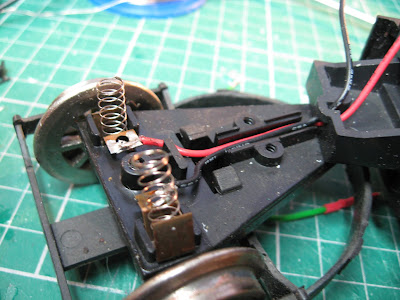
Although it's not essential, I decided to remove all the track power pickups. The pickups on the rear bogie were removed first, by unscrewing the covers over the wires and the contacts for the axle.

The contacts, springs and wires were removed and the cover over the axle replaced.

The three screws over the covers for the wires and axle on the front pony truck were removed.

The wires, springs and contacts were then removed .......

.... and the axle cover replaced.

Again, it wasn't essential, but I decided to remove the contacts on the driving wheels. The bracket holding the motion in place was removed by unscrewing the screw holding it in place. This allowed the cylinders to be removed.

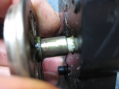
Then the bolts holding the wheels on the axles were removed with a 50mm spanner.

This allowed the fly cranks to be removed.

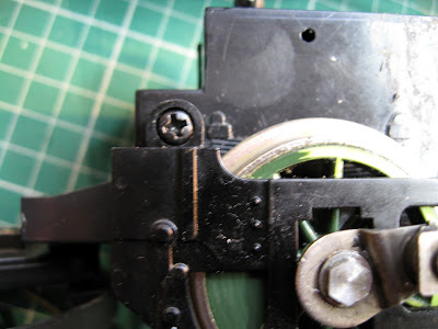
The screws holding the outside frames were then removed.

The motor block was now ready to be dismantled.

The wheels on the side of the motor block with the four screw holes were prised off. They are a push-fit on the gears.

The motor, gears and contact strips were now visible. The motor was removed from its housing - again it is just a push-fit.

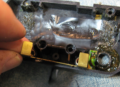
The brass strips over the wheel contacts could then be removed. Once more these are just a push-fit.


 The sheaths, springs and carbon brushes could then be removed.

The vertical contract strips were also removed.

The same process was repeated on the other side of the motor block shell. I was able to inspect the brackets into which the self tapping screws screwed. I had noticed that one of the lower screws was loose when dismantling the motor block clamshell. It was clear that the plastic had sheared. I was in two minds as to whether I should drill through the brackets and replace the self-tappers with bolts and nuts, but I didn't have any bolts long enough. I figured there was sufficient plastic left to allow a longer self-tapping screw to bite. However, before reconverting the loco, I will replace all the self tappers with bolts and nuts. The plastic is clearly too brittle.

The motor block given a good clean-up and then reassembled with fresh grease on the gears. Quartering the motion was actually quite easy as the wheels and flycranks are held in place on square-shaped axles. However, after initially re-assembling the motor block I noticed the fly-cranks weren't opposite the weights on the driving wheels and so had to remedy this.


Wiring up for battery radio control

 Two holes, one 4.5mm diameter and the other 8mm diameter were drilled in the floor of the cab to one side, for the single pole two way switch and the DC charge socket.


These were then wired-up (see wiring diagram)


A Deltang Rx65c was acquired from Micron Radio Control .......

The grey and red leads from the headlamp LED were soldered to P1 (auto front light) and P2 (auto rear light) and a green wire soldered to P5 for the whistle trigger on the soundcard (when the bind button is pressed - Ch5). Brown wires were soldered to the Motor outputs and red and black wires attached to the + and - inputs.

Three 14500 (AA sized) li-ion cells were acquired from Ecolux and wired-up to a 3S li-ion battery protection board. In addition a 4-way JST socket was wired up to each end of the three cells to allow for balance charging (see wiring diagram).

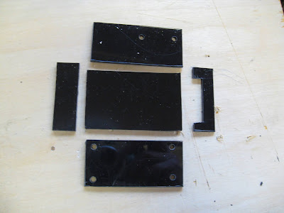
A box was constructed to hold the various components - 45mm x 65mm x 30mm - from 2mm thick black plasticard.

One end was left off the end of the box to allow for the wiring.

 The MyLocoSound steam soundcard was wired-up (see wiring diagram) and a small speaker wired-in.

The Deltang receiver was attached to one side with a cable tie and .....

 the whole assembly was attached to the cab floor with another cable tie.


Circuit diagram


 Reassembly and testing

The body, pony truck and rear bogie were then attached to the motor block and the domes replaced. The model was then given some extensive testing out in the garden.

There were a couple of problems which I encountered. Firstly, the model was initially a bit stiff until the grease worked its way into the mechanism. I also had to ease the motion by bending it slightly to avoid binding. I also discovered that the cow catchers were gathering snow beneath the loco as it negotiated the track and causing it to grind to a halt every so often. You may notice in the reverse run on the video, the cow catchers have been removed which improved running no end.

If I was going to keep the loco in its present form, I would find a way of attaching couplings to the pony truck and rear bogie. The loco is quite long and the outswing on curves is quite dramatic. Again, you will notice on the video that the chain linking the loco to the first track is quite long - it had to be otherwise the loco kept pulling the wagon off the rails each time it negotiated one of my sharp curves.

As indicated above. I intend to remodel the loco - probably based on one of the 4-4-0T locos which ran on the Irish narrow gauge railway system - though I am struggling to find a prototype which matches the driving wheel size (2' 6" in 15mm scale) and wheelbase (4' 7" in 15mm scale).

I may have to make a few compromises and construct a derivative model based on several prototypes rather than a scale model.